Smoke extraction damper ERK-SO
TECHNICAL DOCUMENTATION
Lists |
Construction subject to change
No
return
possible
Version:
2017-11-28
|
Page
43
LISTS
LIST OF FIGURES
Figure 1 - Dimensions ERK-SO .................................................................................................................................................................4
Figure 2 - Actuator housing .....................................................................................................................................................................6
Figure 3 - Opening dimensions of the solid wall ......................................................................................................................................8
Figure 4 - Air flow direction .....................................................................................................................................................................8
Figure 5 - Installation in solid walls ..........................................................................................................................................................9
Figure 6 - Minimum distances of the ERK-SO in solid wall ....................................................................................................................10
Figure 7 - Installation in solid wall without clearance ...........................................................................................................................11
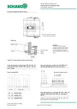
Figure 8 - Installation on solid walls ......................................................................................................................................................14
Figure 9 - Fastening WE-S on ERK-SO and solid wall..............................................................................................................................15
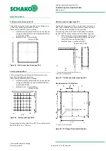
Figure 10 - Opening dimensions of the solid ceiling ..............................................................................................................................17
Figure 11 - Installation in solid ceilings ..................................................................................................................................................18
Figure 12 - Arrangement of WE-S when installed in solid ceilings .........................................................................................................19
Figure 13 - Vertical installation on solid ceiling .....................................................................................................................................20
Figure 14 - Connection to horizontal smoke extraction duct ................................................................................................................21
Figure 15 - Connection in horizontal smoke extraction duct .................................................................................................................21
Figure 16 - Examples of connection to smoke extraction duct ..............................................................................................................21
Figure 17 - Connection on horizontal smoke extraction duct ................................................................................................................22
Figure 18 - Connection to smoke extraction duct made of sheet metal ...............................................................................................23
Figure 19 - Suspension fastening M8 to M12 ........................................................................................................................................24
Figure 20 - Suspension fastenings M16 and M20 ..................................................................................................................................24
Figure 21 - Covered suspending brackets
≤
M12 ...................................................................................................................................26
Figure 22 - Dimensions of the suspension covering ..............................................................................................................................26
Figure 23 - Covered suspending brackets M14 to M20 .........................................................................................................................27
Figure 24: Minimum distances to walls and ceilings and ERK-SO to one another .................................................................................28
Figure 25 - Actuator arrangement and cable routing ............................................................................................................................33
Figure 26 - Profile connection frame type PAR ......................................................................................................................................34
Figure 27 - Security grille type ASG-E ...................................................................................................................................................34
Figure 28 - Flexible connection spigot type FS-E ...................................................................................................................................34
Figure 29 - FS-E flange dimensions/drill pattern ...................................................................................................................................34
Figure 30 - CE marking ...........................................................................................................................................................................38
LIST OF TABLES
Table 1 - Available sizes ...........................................................................................................................................................................5
Table 2 - Dimensions of the actuator housing .........................................................................................................................................6
Table 3 - Usability ....................................................................................................................................................................................7
Table 4 - Accessory packages for vertical damper blade axle position ..................................................................................................12
Table 5 - Accessory packages for horizontal damper blade axle position .............................................................................................13
Table 6 - Number of mounting brackets WE-S for installation on solid wall .........................................................................................16
Table 7 - Arrangement of WE-S and wall fastening for installation on solid wall ..................................................................................16
Table 8 - Suspension (threaded rods) for U-steel for installation on solid wall .....................................................................................16
Table 9 - Number of mounting brackets WE-S for installation in solid ceiling .......................................................................................19
Table 10 - Suspensions ..........................................................................................................................................................................25
Table 11 - Weight table .........................................................................................................................................................................25
Table 12 - Suspension coverings ............................................................................................................................................................26
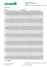
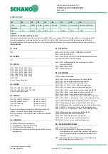
Table 13 - Design data ...........................................................................................................................................................................30
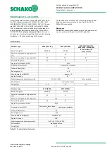
Table 14 - Technical data of actuators ...................................................................................................................................................32
LIST OF DIAGRAMS
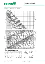
Diagram 1 - Design diagram ..................................................................................................................................................................29

