Smoke extraction damper ERK-SO
TECHNICAL DOCUMENTATION
Technical data - Actuators |
Construction subject to change
No
return
possible
Version:
2017-11-28
|
Page
33
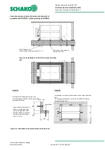
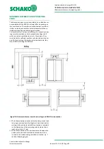
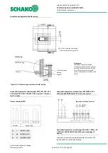
Actuator arrangement and cable routing
Connection diagram for actuator types EK10 (SEL 1.90; 24 V
AC/DC) and EK11 (SEL 2.90; 230 V AC) 2-point or 1-wire con-
trol (7-strand)
Picture showing OPEN
Connection diagram for actuator types EK20 (BE24; 24 V
AC/DC) and EK21 (BE230; 230 V AC) 2-wire control
Connection diagram for actuator type EK12 (SEL 1.90 SLC; 24
V AC/DC) / EK14 (EK12+SPMa-1SR) 2-wire technology (2-
strand)
see safety communication modules power line system SLC,
type SPMa-1SR or SPLM-4S 0SD Mod.
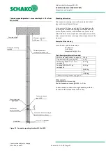
Cover of actuator
housing
Actuator
Please note
The E90 or E30 cable is passed
through the side wall of the actuator
housing (L90) by means of a bore ex-
actly fitting the connection cable
(bore = outer diameter of E90 or E30
cable)
ERK-SO housing
Damper
Actuator
End position
h
Indication of the end positions
S1 + S2 = CLOSED
S4 + S6 = OPEN
SECTION A-A
Figure 24 - Actuator arrangement and cable routing
E90 or E30 cable connection and
cable routing according to DIN

