ASSEMBLY INSTRUCTIONS BIOCLIMATIC PERGOLA
4 DUPLEX COLUMNS
P-150
Page 1: ...ASSEMBLY INSTRUCTIONS BIOCLIMATIC PERGOLA 4 DUPLEX COLUMNS P 150...
Page 2: ......
Page 3: ...LING THE RUBBER 12 1 8 INSTALLING U DRAINING PROFILE OPENING CLOSING CENTRAL AND LATERALS 13 1 9 INSTALLING THE SLAT TRANSMISSION PLATE AND MOTOR TANDEM AXLE 14 1 10 MOTOR INSTALLATION 18 02 ELECTRICA...
Page 4: ...t least AISI 304 stainless steel leaving all bases properly levelled Once the column bases are installed in place measure the diagonal lines to ensure both distances are equal The correct installation...
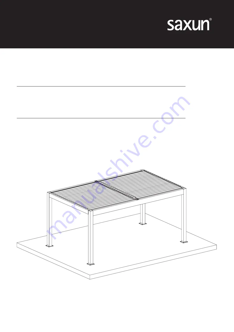
Page 5: ...STRUCTIONS 4 COLUMNS DUPLEX P 150 3 OPENING BEAM CLOSING BEAM FIXING BASE COLUMNS SURFACE PLANE LEFT BEAM RIGHT BEAM CENTRAL BEAM COLUMN A COLUMN B COLUMN D COLUMN C 250 00 250 00 28 00 28 00 144 00 1...
Page 6: ...left and right beam corresponds to the opening and closing In the figure we show the distance from the first pre drilled hole in the opening and in the closing ATTENTION If the pergola is equipped wit...
Page 7: ...the ends of the OPENING beam Join the C and D columns to the ends of the CLOSING beam Use the brackets and screws provided see image Fasten the screws 1 2 and 3 on the inner part of the column use the...
Page 8: ...sten them to the columns bases on the floor surface using the ULS ISO 7380 A2 M6x16 mm screws Proceed as shown in the image CLOSING BEAM OPENING BEAM COLUMN A COLUMN B COLUMN D COLUMN C FIXING SURFACE...
Page 9: ...the A and C columns Follow the screwing sequence Use the brackets and screws provided LEFT BEAM SCREW DIN 7976 A2 M8x50 Code 050198 ARANDELA PLANA DIN 125 A2 M8 Code 022339 COLUMN SIMPLE BRACKET PERG...
Page 10: ...ction Mount the CENTRAL beam between the opening and clos ing beams Match the holes in the top plates of the central beam with the top rivet nuts on the opening and closing beams Simultaneously match...
Page 11: ...crews with the torque indicated in the maintenance section 1 5 ASSEMBLING THE RIGHT BEAM WITH B and D COLUMNS Join the RIGHT beam to the B and D columns Follow the screwing sequence Use the brackets a...
Page 12: ...alant between the contact sides of the OPENING and CLOSING beams and their corresponding sur face manifolds Clip the opening and closing manifolds same profile just in an inverted position You will po...
Page 13: ...50 11 ATTENTION Do not bypass this step it is very important to seal the manifold joint properly sealant provided Create a groove for the water run off at each end of both manifolds use a ham mer and...
Page 14: ...e opposite way to the rest of lasts The clippable closing gutter does not have rubber Installing rubber on the clippable opening gutter Installing rubber on the slats 150 slat step Installing rubber o...
Page 15: ...nd the joints that could suffer water leaks Install the U draining profile on the LEFT and RIGHT beams To do it in sert the profile end through the drain ing hole pre drilled on columns A and B and le...
Page 16: ...etractable stainless steel axle The slats with LED come already pre instaled on one side with a hollow axle The LED connector comes through this axle and it has a protection spring The O 210 retractab...
Page 17: ...the anti friction cap of the right beam so the slat is finally in place ATTENTION Pay attention when installing the slats so there are no errors or confusion in their placement opening closing LED sl...
Page 18: ...mount the motor there is a tandem axle holding the two central transmission plates These have two pre drilled holes and must be installed towards the closing area nearest to the motor area 5th or 6 th...
Page 19: ...hole for LED slats connect the connector and insert it into the beam as shown in the images below As for the other slats the installation is the same inserting the connector axle into the beam with th...
Page 20: ...motor and tandem axles provided but all the pre drilled holes made in the pergo la as well as the screws and pins provided will be adequate for each case 1 10 MOTOR INSTALLATION You should already hav...
Page 21: ...he LED motor and power supply cables so they can be easily connected all voltage 24V Connect the sensors to the side of the controller Use the beam and column caps for the cable insertions and exits r...
Page 22: ...POWER SUPPLY 24 Vdc 3 S1 MOTOR 4 S1 MOTOR 5 S2 LED 6 S2 LED 7 RAIN SENSOR 8 RAIN SENSOR 1 POSITIVE 24V 2 NEGATIVE 24V 3 MOTOR 4 MOTOR 2 1 ELECTRICAL DIAGRAM COMPONENTS 1 motor switchboard with LED and...
Page 23: ...d channel PROG S1 S2 3 Select the profile desired for the motor 4 Press V simultaneously Set up channel my 5 Check the rotating direction open V close If the rotation is not correct reerse the directi...
Page 24: ...utomatically my 11 Stop the movement pressing my my 12 Open the pergola to the position desired in case of snow Press and release V my 13 Confirm the position desired in case of snow by press ing and...
Page 25: ...elease S1 output set up PROG S1 S2 2s 2 Press PROG again to select S2 if LEDs flash 3 times PROG S1 S2 x3 3 Select the profile desired for the motor 4 Press V simultaneously Required output setup my V...
Page 26: ...east once a year or even more often depending on the wind fatigue at the installation site To prevent corrosion it is recommended to periodically clean gutters and sections with neutral soap The minim...
Page 27: ...f the slat shaft and press in to remove the shaft from the beam cap While pressing the shaft pull the slat upwards to remove it from the beam IMPORTANT If the slat being replaced is the closing or the...
Page 28: ...made primarily from recyclable materials It is necessary to be aware of the recycling and disposal sys tems for this kind of product in accordance with the current regulations in your area This symbol...
Page 29: ...water to critical points with a hose or bucket Check tightness of all screws according to tightening chart except the transmission During final installation of motor OK Confirm correct operation of al...
Page 30: ...I M P RGOLA BIOCLIM TICA 4 COLUMNAS DUPLEX P 150 ING 03 0617 saxun com...