background image

39

The Sapling Company, Inc.
1633 Republic Road
Huntingdon Valley, PA 19006
USA

P. (+1) 215.322.6063 
F. (+1) 215.322.8498
www.sapling-inc.com

User Input Installation (3300 Only)

(

IMPORTANT:

 Detach clock from power source before installing new circuitry. DO NOT add new circuitry 

while the clock is operating)

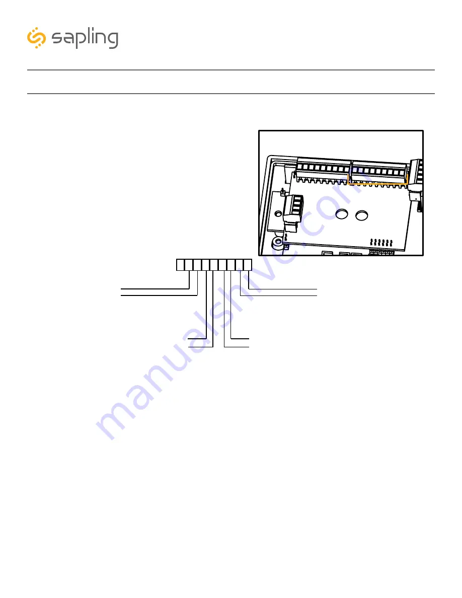
Applying a dry contact closure to any input activates 
that input. To configure what a given input does to the 
clock when activated, refer to the section of this manual 
labeled “Web Interface - Inputs.”

During installation, there is one port blocks mentioned. 
The block on the upper-right will be called J2. Refer to 
the diagram on the right for details. The four available 
inputs are assigned per the diagram below.

1

9

J2

J2-

1 2 3 4 5 6 7 8 9

Input 1

Input 2

Input 4

Input 3

Summary of Contents for SBP-31

Page 1: ...The Sapling Company Inc 1633 Republic Road Huntingdon Valley PA 19006 USA P 1 215 322 6063 F 1 215 322 8498 www sapling inc com Installation Manual V5 0 SBP Series IP Clock Current as of November 2016...

Page 2: ...tion 16 21 Flag Mount Installation 22 29 Double Mount Installation 30 36 Temperature Sensor Installation 37 Buzzer Installation 38 user Input Installation 30 IP Monitor Software Main Screen 40 41 Task...

Page 3: ...clock must be attached to a circuit breaker that can be reset by the user PHYSICAL INJURY HAZARD If you are standing on an object while installing your clock make sure that the object can support your...

Page 4: ...ies clock If your part number begins with SBP 32 you own a 3200 clock If your part number begins with SBP 33 you own a 3300 clock If the second group in your part number ends in S 31S 32S 33S you own...

Page 5: ...is open on Ports 80 123 and 1777 At least one laptop or desktop computer with access to this LAN and a web browser A router for the LAN that operates on the subnet 192 168 0 A copy of the Monitor exe...

Page 6: ...using a PoE Switch 1 Plug in the PoE switch to a power outlet 2 Using a CAT5 or CAT6 data cable connect one end to the switch router on the network and the other end to the IP clock Connecting when u...

Page 7: ...the CD into your computer s CD Drive b Open the file on the CD and select the IPMONITOR application file c Copy the file to your IP Monitor folder 3 If you received the IP Monitor as a web download a...

Page 8: ...access the web interface while the clock is in DHCP mode then there are two ways to find the IP address The first is to press and hold both buttons on the front of the clock simultaneously and releas...

Page 9: ...ble to attach the SBP clock to a PoE injector and the injector to your computer a If you are connecting from the clock to the computer using a PoE switch the injector is not needed 2 If you know the I...

Page 10: ...your network administrator 7 Next to DNS Router set an appropriate IP address The address you enter should be supplied by your network administrator 8 Next to IP Address set an appropriate IP address...

Page 11: ...hould take you to the web interface for that clock Use the password 6063 to enter 2 Select the Clock Settings tab enter an easy to identify name for the clock like the clock s location select the GMT...

Page 12: ...NTP servers listed are the servers you wish to use If you wish enter the URL or IP address of an NTP server or Sapling master clock of your preference If using a Sapling master clock and the master cl...

Page 13: ...the housing and any additional wiring needed to extend the data or ground cables You may also need a 1 4 inch drill if you decide not to attach the clock directly to the gang box If any of the items...

Page 14: ...de of the circuit board If the clock is able to access the Internet it will begin to correct itself Make a note of the clock s Serial Number which should be on a white sticker above the port Add this...

Page 15: ...he left and right inner surfaces of the housing For 4 0 Digit Clocks the holes will be on the top and bottom surfaces 6 Remove the plastic cover from the display board 8 Power the clock if you have no...

Page 16: ...user will also have to provide a Phillips head screwdriver a small flat blade screwdriver a double gang box any equipment needed to install the gang box and any additional wiring needed to extend the...

Page 17: ...be a minimum of three inches away from the ceiling 3 If you do not wish to attach the housing to the gang box proceed to step 4A Otherwise go to step 5 Ceiling 4 Minimum 2 Run a CAT5 or CAT6 data cab...

Page 18: ...e at least 4 inches between the top rear edge of the housing and ceiling Confirm that the bottom of the mounting piece is level with the floor 4B Identify the keyholes towards the top of the back of t...

Page 19: ...screws 4E Use a pencil to trace the holes beneath each keyhole onto the wall Take the clock housing off the wall drill holes at the marked locations and add another two wall anchors 4G Run data cable...

Page 20: ...ess the Internet it will begin to correct itself Make a note of the clock s Serial Number which should be on a white sticker above the port Add this information to your tracking chart 8 Detach the fra...

Page 21: ...to place 10 Remove the plastic cover from the display board 12 Place the housing frame onto the housing You should hear a snapping noise as the latches drop into place 13 Power the clock if you have n...

Page 22: ...al Clock Digital Clock Wall Housing 6 19x1 2 screw 6 32x1 screw Quantity 1 1 4 4 Picture Included in Package Included in Pole Kit SAB 4GD 00S 0 or SAB 1GD 00S 0 If any of the items listed in the kits...

Page 23: ...so have to provide a Phillips head screwdriver a small flat blade screwdriver a double gang box any equipment needed to install the gang box and any additional wiring needed to extend the data or grou...

Page 24: ...e mounting pole by unscrewing the two screws Set the screws and pole aside for later 4 Attach the mounting plate to the gang box using only two of the four long silver 6 32x1 screws With the mounting...

Page 25: ...Flag Mount Installation 5 Remove the mounting pole end cap and the plastic ring from one of the holes 6 Attach the flag mount end cap to the pole Confirm that the covering flap is attached to the sid...

Page 26: ...e of the larger centered holes and the 10 32x3 8 screw 8 Reattach the mounting plate this time using all four long silver 6 32x1 screws then insert the four 8 screws through the mounting plate and int...

Page 27: ...he hole in the adapter Secure the wires by passing them through the wire clamp 12 Insert the four 8 32x7 16 screws through the internal tooth washers then through the adapter and finally into the pole...

Page 28: ...es of the housing For 4 0 Digit Clocks the holes will be on the top and bottom surfaces 15 Attach a data cable to the port on the right side of the circuit board If the clock is able to access the Int...

Page 29: ...on top of the base and the holes for the screws are on the bottom of the base Attach the wires from the pole to the wires in the gang box then use the two black base screws to attach the other side of...

Page 30: ...listed in the kits are missing you may contact your dealer and order a replacement kit Continued on next page Description SBP Digital Clock Digital Clock Wall Housing 6 19x1 2 screw 6 32x1 screw Quant...

Page 31: ...lso have to provide a Phillips head screwdriver a small flat blade screwdriver a double gang box any equipment needed to install the gang box and any additional wiring needed to extend the data or gro...

Page 32: ...he mounting pole by unscrewing the two screws Set the screws and pole aside for later 4 Attach the mounting plate to the gang box using only two of the four long silver 6 32x1 screws With the mounting...

Page 33: ...one of the larger centered holes and the 10 32x3 8 screw 6 Reattach the mounting plate this time using all four long silver 6 32x1 screws then insert the four 8 screws through the mounting plate and i...

Page 34: ...ugh the hole in each adapter Secure the wires by passing them through the wire clamp 10 Insert the four 8 32x7 16 screws through the internal tooth washers then through each adapter and finally into t...

Page 35: ...ing NOTE For 2 5 Digit clocks the holes for the screws will be on the left and right inner surfaces of the housing For 4 0 Digit Clocks the holes will be on the top and bottom surfaces 14 Attach a dat...

Page 36: ...e of the pole on the mounting plate so that the lip is on top of the base and the holes for the screws are on the bottom of the base Attach the wires from the pole to the wires in the gang box then us...

Page 37: ...or Cable is 6 feet 1 83 meters long and so the sensor should be positioned within 6 feet of the clock The cable is unshielded 4 conductor 22AWG 33mm If longer than 6 feet is required the wire would ha...

Page 38: ...steps 1 Attach the long green connector to the J1 Sync Input ports 2 Confirm that the wires are attached to holes 7 and 8 The red wire should be in hole 7 The black wire should be in hole 8 3 Attach...

Page 39: ...is operating Applying a dry contact closure to any input activates that input To configure what a given input does to the clock when activated refer to the section of this manual labeled Web Interfac...

Page 40: ...See the section in this manual labeled IP Monitor Software Task Bar Options 3 Send Message to Digital Clocks Allows the user to generate a message that will be sent to digital clocks a Enter Password...

Page 41: ...ing Upload and Save Configuration on the Quick Access Menu this option lets the user apply the configuration file to other clocks highlighted within the monitor Pressing this button will cause the Dow...

Page 42: ...r to show only the devices that have been added to Group 1 through the Configure Groups menu Configure Groups Opens the group configuration menu see diagram on left a Text Boxes Entering a name into t...

Page 43: ...er By Clock Type By selecting this option the user is able to view specific clock types on the Monitor Screen The clock types users can filter through are Master Clocks Network Repeaters IP Analog and...

Page 44: ...nd Test Email By selecting this option the user is able to send a test email to the email address specified in the Configure Email Alerts option 5 Databases When clicked this button will display the f...

Page 45: ...Send Message to Digital clocks but allows the user to select the number of times that the message will repeat It also provides a longer text box for sending longer messages 7 Send Numeric Message to...

Page 46: ...k have turned gray then the clock was once displayed on the IP Monitor but upon launching the IP Monitor program this most recent time the clock cannot be found on the network 3 Characters are Black W...

Page 47: ...rogram will check the password If the password is correct it will grant the user access to the Web Interface 1 Welcome Sign Displays the Clock name 2 Time Displays the clock s time at the moment the w...

Page 48: ...k will only display the time 6 Seconds Date Displayed The clock will display the date for the number of seconds entered in the box After the selected amount of time passes the clock will change to sho...

Page 49: ...effect Times are entered in 24 hour mode Brightness options are High Medium Low and Off 3 Adjustment 2 Allows the user to set a second time during a given day where the brightness level will change T...

Page 50: ...to be made 5 Clock Name Allows the user to set a unique name for the clock so that it can be identified on the IP monitor The name must be fewer than 20 characters 6 Clock Number Displays the serial n...

Page 51: ...Clock Settings ctd 9 GMT Offset This setting allows the user to set which time zone the clock will use when displaying the time For instance London is an offset of 0 New York is an offset of 5 and Hon...

Page 52: ...ver If DHCP is disabled then the user may set their own static IP address 5 MAC Address This field shows the clock s permanent machine address It cannot be changed 6 DHCP Allows the user to set whethe...

Page 53: ...ock 2 Server Addresses These fields allow a user to set the address that the clock will use to obtain NTP time Web addresses may be entered as a URL or IP number 3 Rotate Servers When left unchecked t...

Page 54: ...s additional details about NTP synchronization when clicked 2 Resync NTP Now This button forces a synchronization with the NTP server when clicked 3 Reset NTP History This button resets all of the dat...

Page 55: ...mit to apply the settings to the clock Example Second Sunday of March at 2 00 Day of the Month This mode allows the user to select the specific day of the month and time for when the clock will switch...

Page 56: ...Alert NTP Synchronization Timeout When selected the clock will send an email alert if the clock hasn t received a time synchronization after the number of minutes listed in the field next to the selec...

Page 57: ...322 8498 www sapling inc com A user may set up and configure the Elapsed Timer control panel through this tab For detailed instructions on the many functions and uses of the Elapsed Timer refer to th...

Page 58: ...Up and Start Activating the input causes the clock to switch from its current display and begin a count up from zero Go to Count Down and Hold Activating the input causes the clock to display and hold...

Page 59: ...e seconds the count up resets to zero and the display goes back to showing the time If a button programmed with the Start Stop function is pressed while Code Blue is running the count up will pause If...

Page 60: ...8 www sapling inc com 1 Clear Log When clicked this button deletes all of the information on the Log page 2 Next When clicked this button displays the next page of log entries Each log entry will disp...

Page 61: ...indicate PM or disappear to indicate AM When the display is set to the 24 hour format the full 24 hour time will appear on the display no other lights should appear Some examples 5 30 AM 12 hour forma...

Page 62: ...ickly press and release the top button and the clock will show the time again Set Time It is possible to manually set the time on the IP Clock However the clock will automatically override the manuall...

Page 63: ...is without power Once power is restored to the clock the display will turn on and display the time on the quartz oscillator It will correct this to accurate synchronized time once a signal from an NTP...

Page 64: ...h a CAT5 CAT5e or CAT6 patch cable May I use any NTP SNTP server for downloading time Yes Any server that sends out Network Time Protocol can be used When I power my clock it seems to be running a tes...

Page 65: ...the clock The clock is not showing the right time What should I do Attempt the following corrections in numerical order until the clock properly synchronizes 1 Confirm that the clock is on the networ...

Page 66: ...by The Sapling Company Inc To Goods which are altered modified or repaired in any place other than a Sapling Company Inc factory or by persons not expressly authorized or approved in writing by The Sa...

Reviews: