-26-
Electrical Adjustments
,
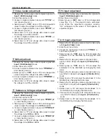
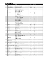
Common Center adjustment
1. Receive the 1 line black/white pattern computer sig-
nal with
Input 1 [RGB(Analog)]
mode.
2. Enter the service mode.
3. Project only green light component to the screen.
4. Select group no. “
200
”, item no. “
18
” and change
data value to obtain the minimum flicker on the
screen.
5. Project only red light component to the screen.
6. Select item no. “
19
” and change data value to obtain
the minimum flicker on the screen.
7. Project only blue light component to the screen.
8. Select item no. “
20
and change data value to obtain
the minimum flicker on the screen.
.
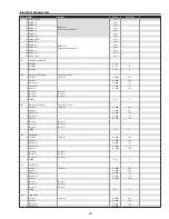
PC Gamma-shift adjustment
1. Receive the 100%whole-white computer signal with
Input 1 [RGB(Analog)]
mode.
2. Enter the service mode.
3. Measure luminance on the screen with the luminance
meter. It is
A
for the reading of luminance meter.
4. Change the signal source to the 50%whole-white
computer signal with
Input 1 [RGB(Analog)]
mode.
5. Select group no. “
200
”, Item no. “
27
” and change the
Data value to make the reading of luminance meter
to be
A x 19%
.
⁄0
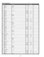
PC White Balance adjustment
1. Receive the 50%whole-white computer signal with
Input 1 [RGB(Analog)]
mode.
2. Enter the service mode, select group no. “
200
”, item
no. “
28
” (Red) or “
29
” (Blue), and change data val-
ues respectively to make a proper white balance.
Confirm that the same white balance is obtained in
video and computer input.
NOTE ON WHITE UNIFORMITY
ADJUSTMENT
If you find the color shading on the screen, please
adjust the white uniformity by using the proper com-
puter and “Color Shading Correction” software supplied
separately. The software can be ordered as follows;
COLOR SHADING CORRECTION Ver. 4.00
Service Parts No.
645 075 9611
⁄1
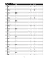
AV Gamma-shift adjustment
1. Receive the 100%whole-white component video sig-
nal (Y/Cb/Cr) with
Input 3 [Y,Pb/Cb,Pr/Cr]
mode.
2. Enter the service mode.
3. Measure luminance on the screen with the luminance
meter. It is
A
for the reading of luminance meter.
4. Change the signal source to the 50%whole-white
computer signal with
Input 3 [Y,Pb/Cb,Pr/Cr]
mode.
5. Select group no. “
210
”, Item no. “
27
” and change the
Data value to make the reading of luminance meter
to be
A x 19%
.
⁄2
PC White Balance adjustment
1. Receive the 100%whole-white component video sig-
nal (Y/Cb/Cr) with
Input 3 [Y,Pb/Cb,Pr/Cr]
mode.
2. Enter the service mode, select group no. “
210
”, item
no. “
28
” (Red) or “
29
” (Blue), and change data val-
ues respectively to make a proper white balance.
Confirm that the same white balance is obtained in
video and computer input.
Summary of Contents for PLV-80 Series
Page 68: ... 68 IC Block Diagrams AD9882 AV A D IC8201 AD8183 AD8185 Selector IC3001 IC2002 ...
Page 69: ... 69 IC Block Diagrams BA7078 Sync Separator IC3007 BH3540 Audo Amplifier IC1652 ...
Page 70: ... 70 IC Block Diagrams L3E06110 S H IC501 IC531 IC561 FA5502 P F Control IC601 ...
Page 72: ... 72 LB1645 Motor Drive IC1631 M62320 I O Expander IC5871 IC5872 IC Block Diagrams ...
Page 73: ... 73 M62399 D A IC1501 IC7801 M62393 D A IC281 IC Block Diagrams ...
Page 74: ... 74 PW388 Scan Converter System COntrol IC301 SP3232 RS 232C Driver IC3801 IC Block Diagrams ...
Page 76: ... 76 IC Block Diagrams TE7780 I O Expander IC4801 ...
Page 114: ... M4YA Nov 2005 BB 400 Printed in Japan SANYO Electric Co Ltd ...

