-2-
Contents
SERVICE MANUAL ................................................... 1
Contents ........................................................................ 2
Safety Instructions ......................................................... 3
SAFETY PRECAUTIONS ........................................... 3
PRODUCT SAFETY NOTICE .................................... 3
SERVICE PERSONNEL WARNING ........................... 3
Specifications ................................................................ 4
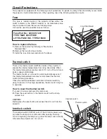
Circuit Protections ......................................................... 5
Fuse ............................................................................ 5
Thermal switch ........................................................... 5
Interlock switch ........................................................... 5
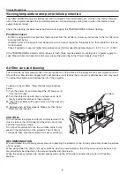
Warning temperature and power failure protection ..... 6
Air filter care and cleaning .......................................... 6
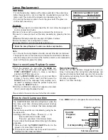
Lamp Replacement ....................................................... 7
How to reset Lamp Replace Counter ......................... 7
How to check Lamp use time ...................................... 7
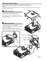
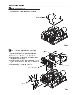
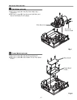
Mechanical Disassemblies ............................................ 8
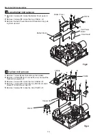
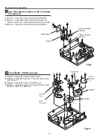
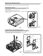
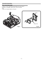
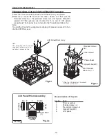
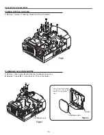
Optical Parts Disassemblies ........................................ 13
LCD Panel/Prism Ass’y Replacement ......................... 18
Adjustments ................................................................. 19
Turning On the Projector ........................................... 19
Adjustments after Parts Replacement ...................... 19
Optical Adjustments ..................................................... 20
Electrical Adjustments ................................................. 23
Service Adjustment Menu Operation ........................ 23
Memory IC Replacement (IC802) ............................. 23
Circuit Adjustments ................................................... 24
Test Points and Locations ......................................... 27
Service Adjustment Data Table ................................. 28
Chassis Description ..................................................... 45
Block Diagrams ......................................................... 45
Chassis over view ..................................................... 45
Input & video precessing stage ................................ 46
LCD panel driving stage ........................................... 47
Audio signal precessing stage .................................. 48
Lamp control stage ................................................... 49
Fan control stage ..................................................... 50
Motor control stage .................................................. 51
Serial bus control stage ........................................... 52
Power supply control & power failure detection ........ 53
LED indicators and projector condition ..................... 54
Power failure detection system ................................ 55
Power failure detection tree ...................................... 56
Error History Log ...................................................... 57
Diagnosis of Power Failure with RS-232C port ......... 58
Diagnosis procedure ................................................. 58
Error information table .............................................. 59
Control Port Functions ................................................. 60
System Control & I/O Port Table ............................... 60
Cleaning ...................................................................... 67
IC Block Diagrams ....................................................... 68
Electrical Parts List ...................................................... 77
Mechanical Parts List ................................................ 108
Cabinet Parts Location ........................................... 108
Optical Parts Location ............................................ 109
Mecanical Parts List ............................................... 113
Diagrams & Drawings ..................................................A1
Parts description and reading in schematic diagram ...A2
Schematic Diagrams ........................................... A3-A10
Printed Wiring Board Diagrams ......................... A11-A16
Pin description of diode, transistor and IC .................A17
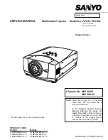
Summary of Contents for PLV-80 Series
Page 68: ... 68 IC Block Diagrams AD9882 AV A D IC8201 AD8183 AD8185 Selector IC3001 IC2002 ...
Page 69: ... 69 IC Block Diagrams BA7078 Sync Separator IC3007 BH3540 Audo Amplifier IC1652 ...
Page 70: ... 70 IC Block Diagrams L3E06110 S H IC501 IC531 IC561 FA5502 P F Control IC601 ...
Page 72: ... 72 LB1645 Motor Drive IC1631 M62320 I O Expander IC5871 IC5872 IC Block Diagrams ...
Page 73: ... 73 M62399 D A IC1501 IC7801 M62393 D A IC281 IC Block Diagrams ...
Page 74: ... 74 PW388 Scan Converter System COntrol IC301 SP3232 RS 232C Driver IC3801 IC Block Diagrams ...
Page 76: ... 76 IC Block Diagrams TE7780 I O Expander IC4801 ...
Page 114: ... M4YA Nov 2005 BB 400 Printed in Japan SANYO Electric Co Ltd ...

