-13-
1
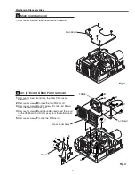
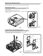
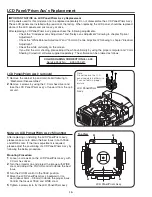
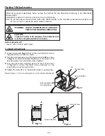
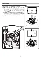
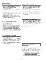
Remove Cabinet Front-Top following to the chapter “Mechanical
Disassemblies”.
2
Loosen 2 screws
A
with 2.5mm hex wrench.
3
Unhook 2 hooks
B
on the both side of the lens and remove the Projection
Lens ass’y off.
Fig.1
Optical Parts Disassemblies
Before taking this procedure, remove Cabinet Top and Main Board following to the “Mechanical Disassemblies”.
Disassembly requires a 2.0mm or 2.5mm hex wrench and a slot screwdriver.
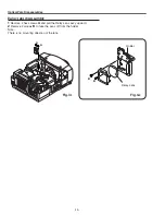
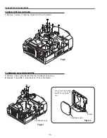
Projection Lens removal
Fig.1-
2
1
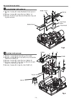
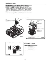
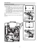
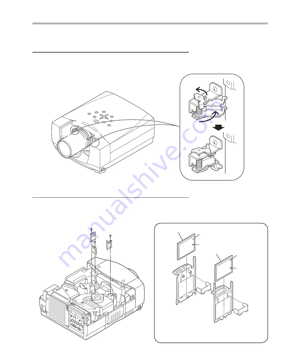
Remove each hex screw and pull the Polarized Glass-In ass’y upward.
2
Remove the stoppers and take the glasses off.
* The B-Plolarised Glass-In ass'y does not provide the Optical filter.
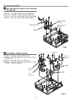
Polarized Glass-In and Optical filter removal
Fig.2-
1
A
A
B
B
Optical Filter(WV)
Polarized Grass
1AV
4Z1
5**
*
1AV
4Z1
5**
*
Part No.
Part No.
Film side
Film side
* Glasses should be placed as the
film sheet attached side comes to
LCD panels side.
Fig.2-
2
Summary of Contents for PLV-80 Series
Page 68: ... 68 IC Block Diagrams AD9882 AV A D IC8201 AD8183 AD8185 Selector IC3001 IC2002 ...
Page 69: ... 69 IC Block Diagrams BA7078 Sync Separator IC3007 BH3540 Audo Amplifier IC1652 ...
Page 70: ... 70 IC Block Diagrams L3E06110 S H IC501 IC531 IC561 FA5502 P F Control IC601 ...
Page 72: ... 72 LB1645 Motor Drive IC1631 M62320 I O Expander IC5871 IC5872 IC Block Diagrams ...
Page 73: ... 73 M62399 D A IC1501 IC7801 M62393 D A IC281 IC Block Diagrams ...
Page 74: ... 74 PW388 Scan Converter System COntrol IC301 SP3232 RS 232C Driver IC3801 IC Block Diagrams ...
Page 76: ... 76 IC Block Diagrams TE7780 I O Expander IC4801 ...
Page 114: ... M4YA Nov 2005 BB 400 Printed in Japan SANYO Electric Co Ltd ...

