-12-
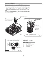
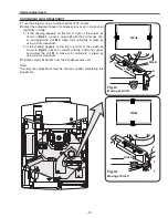
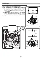
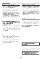
1
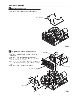
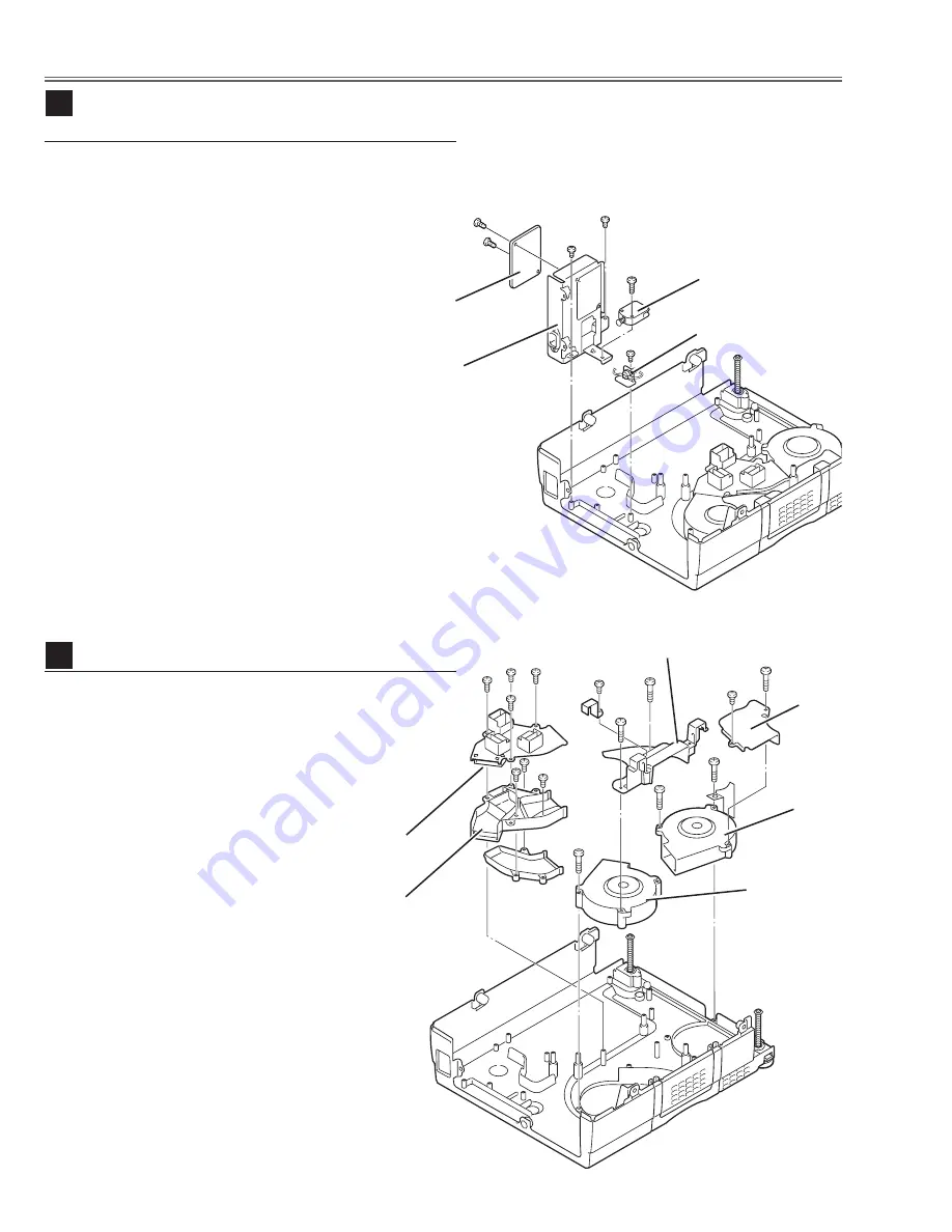
Remove 1 screw
A
to take Interlock Switch(SW905).
2
Remove 2 screws
B
to take Filter Board Holder and
remove 2 screws
C
to take Filter Board from the Holder.
3
Remove 1 screw
D
to take Thermal Switch(SW902).
Mechanical Disassemblies
Fig.9
9
Line Filter Board & Interlock SW & Thermal
SW removal
D
Interlock Switch
(SW905)
Filter Board
C
C
A
B
B
Holder
Thermal Switch
(SW902)
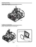
1
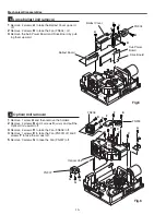
Remove 4 screws
A
to take Air-duct Top off.
2
Remove 1 screw
B
(small) and 1 screw
C
(big) to take
Duct Cover-A.
3
Remove 2 screws
D
to take Fan (FN901) off.
4
Remove 1 screw
E
(small) and 2 screws
F
(big) to take
Air-duct-A and Fan (FN902) off.
Fig.10
10
Fans (FN901, FN902) removal
A
A
A A
B
C
D
D
E
F
F
F
Duct
Cover
-A
FN901
FN902
Air-duct-A
Air-duct
Top
Duct
Cover-B
Summary of Contents for PLV-80 Series
Page 68: ... 68 IC Block Diagrams AD9882 AV A D IC8201 AD8183 AD8185 Selector IC3001 IC2002 ...
Page 69: ... 69 IC Block Diagrams BA7078 Sync Separator IC3007 BH3540 Audo Amplifier IC1652 ...
Page 70: ... 70 IC Block Diagrams L3E06110 S H IC501 IC531 IC561 FA5502 P F Control IC601 ...
Page 72: ... 72 LB1645 Motor Drive IC1631 M62320 I O Expander IC5871 IC5872 IC Block Diagrams ...
Page 73: ... 73 M62399 D A IC1501 IC7801 M62393 D A IC281 IC Block Diagrams ...
Page 74: ... 74 PW388 Scan Converter System COntrol IC301 SP3232 RS 232C Driver IC3801 IC Block Diagrams ...
Page 76: ... 76 IC Block Diagrams TE7780 I O Expander IC4801 ...
Page 114: ... M4YA Nov 2005 BB 400 Printed in Japan SANYO Electric Co Ltd ...

