-12-
■
Optical Parts Disassemblies
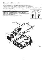
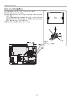
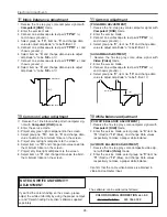
Before taking this procedure, remove Cabinet Top , Cabinet Front and Main Board following to the “Mechanical
Disassemblies”.
Disassembly requires a 2.0mm hex wrench.
1
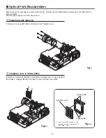
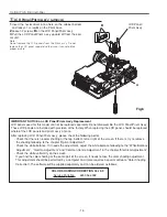
Remove 4 screws (M2.5x8) and remove the Projection Lens.
1
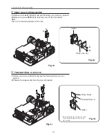
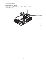
Remove 2 screws
A
(M2.5x5) and pull the Integrator Lens-In ass’y upward.
2
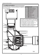
Unhook 4 stoppers
B
and then take the Lens off from the holder.
Fig.1
Integrator Lens
* Lens should be placed as the
rugged surface side comes to
the holder side.
Fig.2-
1
Fig.2-
2
z
Projection Lens removal
x
Integrator Lens-In disassembly
Stoppers
B
A
A
Stoppers
B
Summary of Contents for PLC-XU50
Page 51: ... 51 IC Block Diagrams AD8075 Selector IC201 AN7513 Audio Output IC5601 ...
Page 52: ... 52 BA7078 Sync Separator IC5341 IC Block Diagrams AN5870 RGB SYNC SW IC1201 IC5201 ...
Page 54: ... 54 FA5502 P F Control IC621 IC Block Diagrams CXD3536 LCD Driver IC401 ...
Page 55: ... 55 IC Block Diagrams M62392 M62393 D A IC6271 IC281 ML60851 USB Driver IC9801 ...
Page 56: ... 56 STR Z2156 Power Switching Control IC631 TB1274 Video Decoder IC3101 IC Block Diagrams ...
Page 57: ... 57 IC Block Diagrams TC90A69F Y C Separator IC2101 ...
Page 86: ...MW3 XU5000 MT3 XU5500 86 S5 S5 S5 L9 Projection Mechanical Parts List ...
Page 89: ...MW3 XU5000 MT3 XU5500 89 ...
Page 90: ... MT3A Sep 2003 BB 400 Printed in Japan SANYO Electric Co Ltd ...

