background image

NETWORK settings

45

5

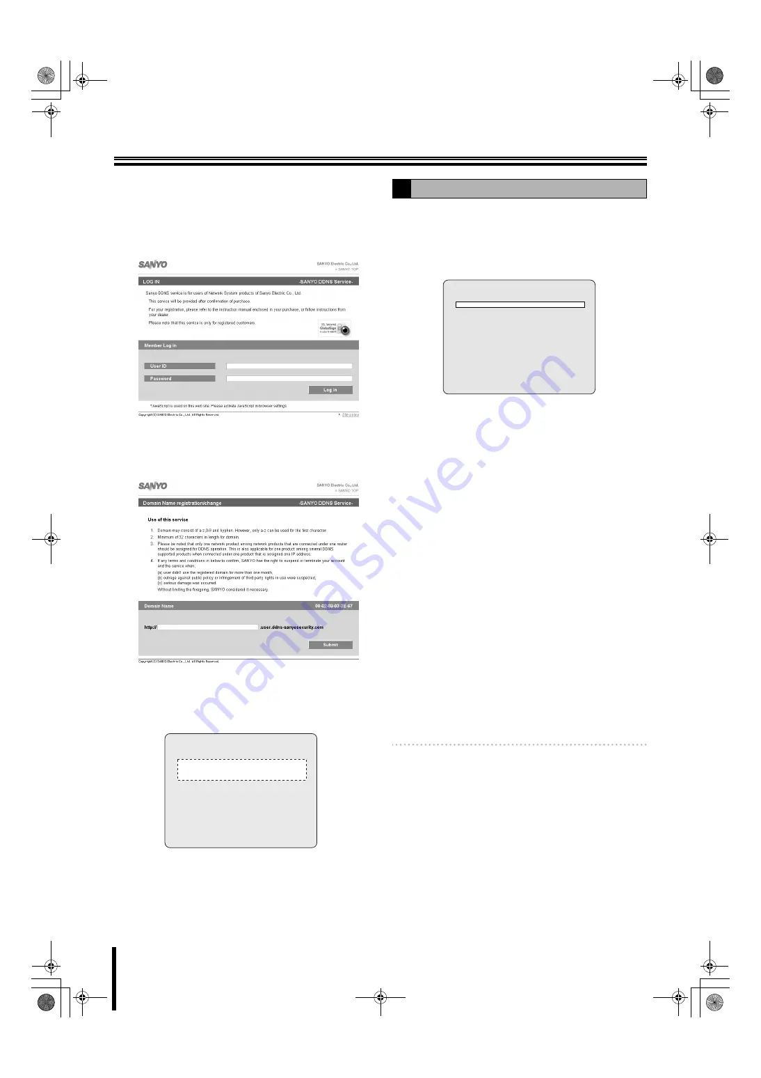
Enter the "USER ID" and "PASSWORD" confirmed 
on the DDNS SERVER SET screen and click the 
Login button.

The domain name registration screen is displayed.

Enter the "

USER ID

" and "

PASSWORD

" in capital 

letters.

6

Enter the domain name to be used and click the 
Submit button.

The domain name is registered to the DDNS server.

7

Return to the DDNS SERVER SET screen of this 
unit and enter the registered domain name.

Select the input location using the control button (

}~

and select a character using the control button (

{|

).

8

Press the ENTER button.

The DDNS settings complete, the screen returns to the 
NETWORK screen.

An E-mail can be sent to a specified IP address.

1

Select "SEND E-MAIL" using the control button 
(

{|

), select "ON" using the control button (

}~

and press the ENTER button.

The SEND E-MAIL screen is displayed.

• ON: 

Enable the sending e-mail function

• OFF: 

Disable the sending e-mail function

2

Select the following item using the control button 
(

{|

) and select the setting using the control 

button (

}~

).

• IP NOTIFICATION: 

ON: 

Does not send a notification E-mail even when 
an event alarm is triggered.

OFF: 

Does not send an E-mail

• EVENT ALARM: 

OFF: 

Does not send a notification E-mail even when 
an event alarm is triggered.

ALARM: 

A notification e-mail is sent when ALARM 
recording is triggered by the sensor connected to 
the external alarm input terminal (ALARM IN) of 
the unit.

MOTION: 

A notification e-mail is sent when MOTION 
recording is triggered by a movement detected by 
the motion sensor built into the unit.

ALL: 

A notification e-mail is sent when a recording is 
triggered either by an external alarm or the 
built-in motion sensor.

Memo: 

EVENT ALARM requires setting of ALARM-SET. 
(P32)

3

Select the following item using the control button 
(

{|

) and set the information, such as the E-mail 

address, using the control button (

{|}~

).

Pressing the EXIT/STOP button returns the screen to 
the SEND E-MAIL screen.

DDNS SERVER SET

   - - - - - - - - - - - - - - - -

   - - - - - - - - - - - - - - - -

USER ID   XX-XX-XX-XX-XX-XX

PASSWORD  XXXX-XXXX-XXXX

LOG                       

ready

F

Setting the SEND E-MAIL

SEND E-MAIL

IP NOTIFICATION

OFF

EVENT ALARM

OFF

MAIL TO

MAIL SERVER 

  USER

  PASSWORD

MAIL FROM

L8HBT_WA(DSR-2116_2108)(GB).book  45 ページ  2009年5月27日 水曜日 午後4時50分

Summary of Contents for DSR-2108

Page 1: ... INSTRUCTION MANUAL Die BEDIENUNGSANLEITUNG in den Sprachen Deutsch Französisch Spanisch und Italienisch finden Sie auf der beiliegenden CD ROM Utilisez le CD ROM fourni pour consulter le MANUEL D INSTRUCTIONS en allemand français espagnol et italien Consulte en el CD ROM suministrado el MANUAL DE INSTRUCCIONES en alemán francés español e italiano Per il MANUALE DI ISTRUZIONI in Tedesco Francese S...

Page 2: ...etting the LOAD DEFAULT 37 D Setting an ADMIN PASSWORD 38 E Setting the USER PASSWORD 39 F Setting a NETWORK PASSWORD 39 G Setting the DATE FORMAT 40 H Setting the CLOCK SET 40 I Setting the RS485 SET 40 J Setting the PTZ CONTROL 40 K Setting the LANGUAGE 40 L Setting a REMOTE CONTROL ID 41 NETWORK settings 42 A Setting the PORT 42 B Setting a CLIENT ACCESS 42 C Setting the BANDWIDTH SAVING 42 D S...

Page 3: ...al carefully and retain it for future reference Should the unit require maintenance contact an authorized service center Use of controls adjustments or the performance of procedures other than those specified herein may result in hazardous radiation exposure To prevent direct exposure to laser beam do not try to open the enclosure Visible laser radiation when open DO NOT STARE INTO BEAM This class...

Page 4: ... connected unit does not exceed the electrical rating of the extension cord Higher power consumption may result in heat generation and cause fire b Disassembly prohibited Do not place your hand inside this unit as this may cause fire and or electrocution Consult the dealership where this unit was purchased or factory shop for diagnostics adjustments and repairs b Do not place any foreign objects i...

Page 5: ...ower plug with wet hands Doing so may result in electrocution b Do not sit on Doing so may cause the unit to fall be damaged and or result in injury b Make sure the cables are connected properly Connect and install the power cable and connection cable very carefully Tripping over the cable may result in the unit capsizing or falling and cause injury b Do not place heavy objects on connected units ...

Page 6: ...exposed to extreme temperatures 10 degrees C per hour or humidity changes b Points on unit positioning This unit is constructed using precision electronic parts Avoid placing it in areas described below as this may cause faulty operation and or breakdowns In direct sunlight In places exposed to water In the vicinity of cooling and heating units or humidifiers Near the air conditioner where the uni...

Page 7: ...Maintaining this unit Turn the power off and remove the power plug from the outlet Wipe away any dust using a soft cloth When the stains are hard to remove Soak a cloth in water with diluted neutral detergent and wring it Wipe the stain with the moistened cloth and finally dry off with a dry cloth CAUTION Do not use paint thinner benzine or any other alcohol based agents for cleaning The exterior ...

Page 8: ...ife expectancy of each part depends on the environment in which the unit is used However the head and motor are particularly prone to wear and deterioration Therefore writing errors are more likely to occur after two years of use b Cooling fan 3 years 25 C environment Cooling fan failure causes higher internal temperatures which may result in a faulty hard disk Periodically check whether the cooli...

Page 9: ...wer has been turned off The unit is further susceptible to damage through shock and vibration during that period It is imperative that you do not move the unit during that time G Do not expose to shock or vibration Avoid placing this unit directly on the floor Make sure that the four stands attached to the base of this unit are used when placing it on the floor G Always use the original packaging ...

Page 10: ...ing mode I Search button SEARCH P22 Switches to recorded images searching mode J Pan Tilt Zoom button PTZ P14 Operates the Pan Tilt Zoom Focus mode of the PTZ dome camera K Camera channel selection buttons P12 The video of the selected channel is displayed on single screen Also used to enter a password L Menu button MENU P9 30 Displays the settings menu screen and switches to setting mode M Exit S...

Page 11: ...y signal is output to one or more external alarm devices connected to the alarm output terminals These terminals are normally open I Cooling fan J Power socket Basic connections Do not turn this unit on before all the connections are complete Read the instruction manual of each unit carefully Make sure each unit is connected properly as faulty connection may result in the unit emitting smoke and o...

Page 12: ... information on how to connect Memo The type of network must be set on the NETWORK screen P42 Network connection LAN LAN connection POWER MODE AUTO MENU Camera Sold separately Monitor Sold separately Computer Switching hub Ethernet cable Straight cable POWER MODE AUTO MENU Computer Monitor Sold separately Camera Sold separately Cross type Internet DHCP ADSL connection POWER MODE AUTO MENU Camera S...

Page 13: ... with a RS 485 control terminal is connected the camera can be directly operated through this unit Memo The settings on the PTZ CONTROL screen and RS 485 SET screen in the system setting are necessary when a camera is connected P14 40 Connection to the RS 485 control terminal is unnecessary for coaxial superimposed type COAX cameras Select a protocol for COAX in the PTZ CONTROL settings P14 Connec...

Page 14: ...rity reasons make sure you change the default ADMIN PASSWORD P38 3 Press the ENTER button The SHUTDOWN confirmation screen is displayed 4 Select CONFIRM with the control button 5 Press the ENTER button The power shuts down and the power indicator turns orange 2 1 2 5 3 4 A Switching the power on Do not press the power button during initialization This may result in data loss NO VIDEO CH6 NO VIDEO ...

Page 15: ...to the left of the capacity display lights to indicate that the unit is in the overwriting mode 6 Date and time display This unit manages the recorded videos according to their date and time Make sure the correct date and time are set in the CLOCK SET P9 7 Camera channel display Select display hide channel in OSD in LIVE settings P31 8 Recording display Factory default settings start continuous re...

Page 16: ...onnecting a PC monitor to the VGA terminal 1 Press the MENU button The PASSWORD input screen is displayed To return to the previous screen press the EXIT STOP button 2 Enter the ADMIN PASSWORD using the channel selection buttons The MAIN MENU screen is displayed 1111 is the factory default setting password 2 3 1 9 A Setting the television system and the monitor output Cannot be used when PAL and N...

Page 17: ... the daylight saving start date is set 4 Set the daylight saving end date using the same procedure 7 Select the display date and time using the control button 8 Select the item using the control button set the date and time using the control button and press the ENTER button The update time confirmation screen is displayed After you confirm the screen select CANCEL or CONFIRM using control button ...

Page 18: ...vice you connected When multiple devices are connected make the termination switch OFF except the first and last devices that you connected B NO VIDEO CH6 NO VIDEO CH2 NO VIDEO CH10 NO VIDEO CH14 NO VIDEO CH5 C CH1 NO VIDEO CH9 NO VIDEO CH13 NO VIDEO CH7 NO VIDEO CH3 NO VIDEO CH11 NO VIDEO CH15 NO VIDEO CH8 NO VIDEO CH4 NO VIDEO CH12 NO VIDEO CH16 2009 05 03 09 04 54 2 A INTIALIZING Ver XXXXXX XX ...

Page 19: ... QUAD button The videos of cameras 1 4 are displayed on quad screen 2 Press the QUAD button again The videos of cameras 5 8 are displayed on quad screen Each time pressing the QUAD button the video of the camera changes as the quad screen A C D B A Single screen display CH2 C 2009 05 03 09 04 54 2 A 2 B Quad screen display CH1 C CH3 CH2 C C C CH4 2009 05 03 09 04 54 2 A 06 05 08 07 02 01 04 03 06 ...

Page 20: ...input the audio also switches in channel sequence order When using single screen display In DSR 2108 single screens 1 to 8 are displayed in sequence When using quad screen display In DSR 2108 the unit of 4 screens 1 to 4 and 5 to 8 are displayed in sequence Memo The sequence interval from one camera video to another can be set P31 Automatic camera sequencing is not available when using multi 8 mul...

Page 21: ...tton The control screen is displayed 3 Controlling the camera Control functions available differ according to the camera model b Pan Tilt operations 1 Select PAN TILT using the control button and press the ENTER button 2 Adjust the tilt position using the control button and adjust the pan position using the control button 3 To perform automatic panning press the ENTER button The following message ...

Page 22: ...ght key Iris Close Open Enter key Tour Sequence OFF b Camera menu settings 1 Select MENU using the control button and press the ENTER button 2 Select a menu using the control button and select a setting value using the control button 3 To switch to the next screen or validate a setting value press the ENTER button The following message is displayed on the screen Up Down key Cursor Up Down Left Rig...

Page 23: ... recording by overwriting earlier data even when the hard disk capacity is full OFF Stops recording operations once the hard disk capacity is full 1 To manually start recording press the REC STOP button while monitoring live video R is displayed on the recording display and recording starts Memo When operated manually the unit records according to the settings for real time recording REAL TIME REC...

Page 24: ...ol button and select the level of sensitivity using the control button Selections 1 9 Low sensitivity 6 Select PRE RECORD using the control button and select the pre recording as necessary using the control button 7 Select POST EVENT RECORD using the control button and select the recording time as necessary using the control button Selections 2 30 SECONDS 1 5 MINUTES 10 MINUTES 15 MINUTES 8 Press ...

Page 25: ... pre recording as necessary using the control button 6 Select POST EVENT RECORD using the control button and select the recording time as necessary using the control button Selections 2 to 30 SECONDS 1 to 5 MINUTES 10 MINUTES 15 MINUTES 7 Press the EXIT STOP button once operations are complete Press the EXIT STOP button repeatedly to return to the live screen Memo Set the alarm input conditions us...

Page 26: ... Press the EXIT STOP button once operations are complete Press the EXIT STOP button repeatedly to return to the live screen E SCHEDULE recording RESOLUTION CHANNEL FRAME RATE QUALITY The following settings are necessary when performing sensor detection MOTION ZONE MOTION SENSITIVITY PRE RECORD POST EVENT RECORD RECORD RESOLUTION FULL CHANNEL FRAME RATE 1 ips QUALITY NORMAL RECORDING SCHEDULE MOTIO...

Page 27: ...n The TIMER SET CH2 screen is displayed The CH1 schedule is copied to CH2 E Example 1 Copying the channel 1 schedule to channel 3 COPY FROM 0 3 6 9 12 15 18 21 ALL SUN MON TUE WED THU FRI SAT TIMER SET CH1 COPY FROM CH1 COPY TO CH1 C M A C M A C M A A C M A C M A C M A A C M A C M A C M A A M C M A C M A C M A A M C M A C M A C M A M C M A C M A C M C A M C M A C M A C C 0 3 6 9 12 15 18 21 ALL SU...

Page 28: ...H P22 Search through a recorded video list by setting the date on the calendar display the camera channel and specify the type of recording b BOOKMARK P25 Searches through the bookmarked still images or moving videos b The function of each button during playback e The fast forward speed changes each time it is pressed the symbol is displayed on the bottom right of the screen c Standard 2e X2 4e 8e...

Page 29: ...ed type of recording is displayed in red If the 4 letters are displayed in red all the type of recordings have been selected M Recording activated by motion detection MOTION A Recording activated by an external alarm input ALARM R Real time recording C Continuous recording CONTINUOUS Example Searching recordings activated by the motion detection M of the channel 2 of the camera The list screen is ...

Page 30: ...track a timeline appears next to the bottom line AUDIO 4 Move the yellow cursor of the HOUR scale to the specified period using the control button and press the ENTER button The HOUR scale cursor turns light blue and the timeline of the head channel of the MINUTES scale turns yellow 5 Select the channel to be played using the control button The timeline of the selected channel is displayed in yell...

Page 31: ...rol button and press the ENTER button The LOG screen is displayed If recordings are available the date is displayed in red Indicates that there are recordings in the previous month Indicates that there are recordings in the next month Moving the cursor to the day of the first recording in the month displayed by the calendar and pressing the button displays the previous month of the calendar Moving...

Page 32: ... the previous month of the calendar Moving the cursor to the day of the last bookmark in the month displayed by the calendar and pressing the button displays the next months of the calendar 3 Select an event which date is displayed in red using the control button and press the ENTER button LIST is displayed 4 Select the date to be played back from the list using the control button and press the EN...

Page 33: ...RK COPY button is pressed Search display of marked still image can be performed using BOOKMARK in the search menu P25 3 Select the recording media USB stick or CD RW onto which the video should be copied using the control button and press the ENTER button The message SAVING is displayed and copying starts When copying is complete the message SAVE SUCCESS is displayed Memo If the specified recordin...

Page 34: ...OKMARK in the search menu P25 6 Select the recording media USB stick or CD RW onto which the video should be copied using the control button and press the ENTER button The message SAVING is displayed and copying starts When copying is complete the message SAVE SUCCESS is displayed Memo If the specified recording media has not been inserted or there is a problem with the media type or state of the ...

Page 35: ... is 1111 3 Press the ENTER button The security lock is set and the blue security lock icon is displayed b Canceling the security lock 1 Press the EXIT STOP button for approximately 5 seconds The password entering screen is displayed 2 Enter the ADMIN PASSWORD using the channel selection buttons 3 Press the ENTER button The security lock is cancelled and the blue security lock icon disappears PASSW...

Page 36: ...03 09 04 54 2 A PASSWORD CH1 2009 05 03 09 04 54 2 A 1 1 NETWORK PORT 5445 CLIENT ACCESS ON BANDWIDTH SAVING ON NETWORK TYPE LAN IP 0 0 0 0 SUBNET MASK 0 0 0 0 GATEWAY 0 0 0 0 DNS 0 0 0 0 DDNS OFF SEND E MAIL OFF NTP SET OFF b LIVE settings P31 To perform adjustments related to live videos monitoring such as sequencing settings and each camera video adjustments b RECORD settings P35 To perform adj...

Page 37: ...tton once operations are complete Press the EXIT STOP button repeatedly to return to the live screen Memo The contents of the settings are saved when leaving the menu setting screen Even if the power is turned off the settings content are retained 2 2 1 6 5 CH1 PASSWORD 2009 05 03 09 04 54 2 A 1 10 CH1 C PASSWORD 2009 05 03 09 04 54 2 A MAIN MENU RECORD LIVE SYSTEM HDD SET NETWORK SERVICE RECORD R...

Page 38: ...ng the control button The display bar 20 100 changes and the contrast of the real time character display changes To set the sequence and the sequence interval of the screen 1 Select SEQUENCE using the control button and select ON using the control button ON Sequencing is performed on a single or quad screen When live OFF Sequencing is not performed 2 Select SEQUENCE DWELL TIME using the control bu...

Page 39: ... 0 100 Setting the SATURATION To select SATURATION and adjust the saturation of the video The saturation of the images changes in real time 0 100 Press the EXIT STOP button once operations are complete Press the EXIT STOP button repeatedly to return to the live screen Sets the alarm input output conditions of the alarm input output terminal 1 Select ALARM SET using the control button and press the...

Page 40: ...ect TYPE using the control button 2 Set the signal polarity using the control button Does not react N OPEN Normal Open Normally open reacts when closed N CLOSE Normal Close Normally closed reacts when opened Sets the output conditions of the monitor video terminal MON2 1 Select MON2 OUT using the control button and press the ENTER button The MON2 OUT screen is displayed 2 Setting the output condit...

Page 41: ...utton 2 Select the setting position using the control button If MON2 TYPE is set to FULL set one channel if it is set to QUAD set 4 channels 3 Select a channel 1 16 using the control button In DSR 2108 CH1 CH8 4 Move the cursor back to MON2 CHANNEL using the control button If SEQUENCE is set to ON 1 Select MON2 CHANNEL using the control button 2 Select a channel using the control button The factor...

Page 42: ...REAL TIME REC SET 1 1 B Setting a CHANNEL Depending on the RESOLUTION settings the total FRAME RATE available is limited as follows If the total exceeds the limit the FRAME RATE of other channels cannot be set If FULL is selected under resolution setting NTSC It is possible to select up to a total of 30 frames for channels 1 to 8 and up to a total of 30 frames for channels 9 to 16 PAL It is possib...

Page 43: ...to 30 SECONDS 1 to 5 MINUTES 10 MINUTES 15 MINUTES Setting the AUDIO To select AUDIO and set the audio sound recording ON Records the audio of live videos To listen to audio sound connect an external microphone or speaker OFF Does not record the audio of live videos To perform SCHEDULE settings The recording schedule of each channel can be set using settings by the hour P19 To trigger recording us...

Page 44: ... HDD To return to the factory default settings of the unit 1 Select LOAD DEFAULT using the control button and press the ENTER button The LOAD DEFAULT screen is displayed 2 Select CONFIRM using the control button and press the ENTER button The screen switches to the INITIALIZING screen The live video is displayed on the monitor A Setting the DVR ID SYSTEM DVR ID DVR DESCRIPTION LOAD DEFAULT ADMIN P...

Page 45: ... is displayed Input the correct password again b Settings for no password It is possible to enter the menu settings screen without inputting a password 1 Select ADMIN PASSWORD using the control button and press the ENTER button The Current password input screen is displayed 2 Enter the current password using the camera selection button and press the ENTER button The New password input screen is di...

Page 46: ...istrators and general users The operations with USER PASSWORD are limited to search and playback No user password is set by factory default Set a password different from ADMIN PASSWORD 1 Select USER PASSWORD using the control button and press the ENTER button The Current password input screen is displayed 2 The following setting method is identical to the one described in Setting an ADMIN PASSWORD...

Page 47: ...n The RS485 SET screen is displayed 2 Select the item to be set using the control button and select a setting value using the control button DATA SPEED 2400 4800 9600 19200 ADDRESS 0 128 Refer to Operating the PTZ dome camera P14 Refer to Setting the language LANGUAGE P11 G Setting the DATE FORMAT H Setting the CLOCK SET I Setting the RS485 SET J Setting the PTZ CONTROL K Setting the LANGUAGE RS48...

Page 48: ...ol and press 04 using the numeric buttons The remote control display reappears the ID number 04 set in the SYSTEM settings allows the operation of this unit Memo The remote control ID 04 currently in use is displayed on the monitor screen If no remote control ID has been set A ALL is displayed L Setting a REMOTE CONTROL ID CH1 R 2009 05 03 09 04 54 2 A SYSTEM DVR ID DVR DESCRIPTION LOAD DEFAULT AD...

Page 49: ...trol button and set ON using the control button ON Accessing the unit via a PC using the supplied exclusive software OFF Does not allow access Set if the network bandwidth is not large enough when monitoring live videos Select BANDWIDTH SAVING using the control button and set the settings using the control button ON Live videos advance frame by frame At the rate of 1 frame per second OFF Does not ...

Page 50: ...ssword by moving the cursor to each digit with the control button then press the ENTER button The screen returns to the NETWORK screen 5 Press the EXIT STOP button The APPLY NETWORK ADDRESS screen is displayed 6 Select CONFIRM using the control button and press the ENTER button Once the settings are complete restart the unit The screen switches to live video D Setting the NETWORK TYPE NETWORK PORT...

Page 51: ...s unit was purchased or a Repair Service Center 2 Select DDNS SERVER SET using the control button and press the ENTER button The DDNS SERVER SET screen is displayed 3 Confirm the USER ID and PASSWORD displayed on the screen Ensure that the USER ID and PASSWORD are written down as they are required to register the domain name 4 Start Internet Explorer on the computer and access Sanyo s DDNS service...

Page 52: ...g using the control button IP NOTIFICATION ON Does not send a notification E mail even when an event alarm is triggered OFF Does not send an E mail EVENT ALARM OFF Does not send a notification E mail even when an event alarm is triggered ALARM A notification e mail is sent when ALARM recording is triggered by the sensor connected to the external alarm input terminal ALARM IN of the unit MOTION A n...

Page 53: ...ime OFF NTP server not used for adjusting time 2 Select the following item using the control button and press the ENTER button Set the NTP server address using the control buttons and press the ENTER button NTP SERVER ADDRESS1 NTP SERVER ADDRESS2 3 Select TIMEZONE using the control button and the time zone using the control button Selections GMT 1 00 to 12 00 0 00 to 13 00 4 Select TIME TO SYNCHRO...

Page 54: ...rol button and press the ENTER button The FORMAT screen is displayed 2 Select CONFIRM using the control button and press the ENTER button Formatting starts Once formatting is complete the unit restarts and returns to live videos HDD SET OVERWRITE ON FORAMT AUTO DELETE OFF AUTO DELETE DAYS 30 DAYS MAIN MENU RECORD LIVE SYSTEM HDD SET NETWORK SERVICE A Setting the OVERWRITE When OVERWRITE is set to ...

Page 55: ...on is enabled OFF The auto delete function is disabled 2 Select AUTO DELETE DAYS using the control button and set the storage period using the control button If AUTO DELETE is set to ON set a recording data storage period Selection 2 3 4 60DAYS C Setting the auto delete function The recording data beyond the set period cannot be played back HDD SET OVERWRITE ON FORAMT AUTO DELETE OFF AUTO DELETE D...

Page 56: ...Select LOAD SETUP FROM A USB using the control button and press the ENTER button The confirmation screen is displayed 3 Select CONFIRM using the control button and press the ENTER button The message LOADING is displayed and loading starts Once loading is complete the unit restarts and returns to live videos Select DISK INFO using the control button and press the ENTER button The following data is ...

Page 57: ...1024 768 Disk capacity 10 MB More than 2 1GB when using Sanyo recording software Operating System Windows VISTA Windows XP Professional SP2 Windows XP Home Direct X Direct X 8 1 or above Install using the interactive screen 1 Insert the supplied CD ROM in the CD drive and double click Sanyo Client exe The installer runs 2 Confirm the installation destination folder on the Choose Destination Locati...

Page 58: ...nput the folder name in the box directly or select a folder from the Existing Folders list 5 The software starts installing The progress of the installation is displayed on the Setup Status screen 6 Installation is complete Once the installation is complete the DVR Utility 2000S shortcut icon is displayed on the desktop Double click this icon to start the software Specify SANYO DVR Utility 2000S i...

Page 59: ...nnected the connect button on the operation panel changes to the disconnect button Clicking this button disconnects the connection with this unit and the displayed video disappears In DSR 2108 the multi screen switch button displays a multi 8 screen b When there are several connections The connection information used with this unit is displayed at once under the site name in the Select Site pull d...

Page 60: ... A ALARM recording in progress P18 3 Bottom right R Recording in progress 4 Bottom left A Alarm output in progress P54 Memo Video is shown in the same channel as the alarm output terminal number 2 Information display area The following information is displayed 1 Shows the used capacity of the hard disk of this unit 2 Communication bit rate and frame rate To display set in the set up menu in the ge...

Page 61: ...en display Switching to quad screen display SW For Pan Tilt operations For Zoom Focus operations SW The audio is not output The audio is output Adjusts the output volume VOLUME SW Sets recording function to ON Recording to PC hard disk Sets recording function to OFF SW Freezes the live video on PC Unfreezes the live video on PC Switches the alarm output ALARM OUT 1 on the back panel to ON OFF A Th...

Page 62: ...e operation panel The video of the cameras connected to this unit is displayed on multi 16 screen or multi 9 screen In DSR 2108 the only available multi screen is multi 8 screen Memo Each time the button is clicked the display switches in turn from the multi 16 screen to the multi 9 screen 2 patterns video Memo About selecting a camera video If a live video is selected clicked on the quad screen o...

Page 63: ...is started Recording is performed automatically in the selected mode even without operating the recording button on the operation panel Memo Set the automatic recording or select a recording mode on the recording settings screen in the set up menu P65 Network operation video recordings are all saved on the PC hard disk Set the save conditions in the disk settings screen in the set up menu P65 No c...

Page 64: ...he audio button on the operation panel Allows the user to save live video or playback video displayed on the screen on the PC as still images 1 Selecting the camera video to be saved When in quad screen display select 1 camera video and click a red frame surrounds the selected camera or double click to switch to single screen display 2 Click CAPTURE on the operation panel The Image capture dialog ...

Page 65: ...nd click a red frame surrounds the selected camera or double click to switch to single screen display 3 Operates the camera using the camera controller on the operation panel Clicking the controller button switches the controller display b For Pan Tilt operations b For Zoom Focus operations F Operating the PTZ dome camera Adjusts the tilt Adjusts the pan Switches the controller button to Zoom Focu...

Page 66: ...ropped to the left or to the right or when clicking on the scale 2 Display unit Switches the mark unit of the scale HOUR One hour X 24 marks MINUTE 5 minutes X 12 marks 3 Backup operation button START POINT Sets the start point of the video range to be backed up END POINT Sets the end point of the video range to be backed up BACK UP Executes the backup DVR PC Switches the recorded video search des...

Page 67: ...emo Switching the display unit of the scale from HOUR to MINUTE allows the user to further narrow down the time slot with recorded video 4 Specify the playback start point Drag and drop the slide knob of the time scale and move it to the playback start point 5 Click the playback button 1 The video starts playing During the playback the playback operation buttons allow such operations as fast forwa...

Page 68: ...e channel to be backed up However channels without recorded video are skipped In DSR 2108 CH1 CH8 2 Start time End time Can be modified using the spin buttons 3 File Path The path set in the general settings screen in the set up menu is displayed P62 4 Automatic reconnection If the checkbox is checked backup continues after reconnecting even if the network gets disconnected during backup If the ch...

Page 69: ...n password Old Password Input the current password New Password Input the new password Confirm Password Re input the new password to confirm the password Click OK after inputting the password 3 Save Path Set the destination folder for still video Capture and backup video Backup 4 Miscellaneous Automatic reconnection If the checkbox is checked reconnection operations are performed automatically aft...

Page 70: ... name The specified name is displayed on displays such as the camera video Set a channel name for each channel following the same procedure 6 Click OK The Addition dialog close and the site is added to the Site list b Modify the registered content Modify 1 Click the site to be modified in the Site list The line of the selected site is highlighted in blue 2 Click Modify The Modify dialog is display...

Page 71: ...older to be searched using Path 2 Set the start point of the search range in From If the checkbox First is checked it is automatically set to the first date and time in the folder 3 Set the end point of the search range in To If the checkbox Last is checked it is automatically set to the newest date and time in the folder 4 Click Find The event information of the specified range is displayed as a ...

Page 72: ...ed on the back panel of this unit the event is recorded on the PC Recording duration Duration Unit seconds 3 Channel Specify the camera to be recorded using the checkbox Memo Using All of the checkbox the user can check or uncheck all the cameras Click OK once the above settings are complete The content of the settings are confirmed and saved Set the capacity and the drive of the PC where the reco...

Page 73: ...message is displayed on the Success dialog and the setting sent to the DVR Click OK and close the dialog 1 Clicking Apply The Remote Setup screen remains displayed even after the Success dialog is closed Close the Remote Setup screen by clicking OK upon completing all of the remote setup operations 2 Clicking OK Closing the Success dialog also closes the Remote Setup screen 3 Clicking Cancel If a ...

Page 74: ...ets the interval 1 60 SECONDS for automatically switching the screens 4 Event Beep Setting for sounding an alarm in the event of an alarm ON Alarm sound enabled OFF Alarm sound disabled 5 OSD Contrast Adjusts the character contrast on the screen b Channel specific settings These settings apply to the specified channel only 1 Channel designation CH1 CH16 In DSR 2108 CH1 CH8 2 Display Sets whether t...

Page 75: ...4 Video Loss On Outputs an alarm signal when a video loss occurs in the specified video input terminal Input terminal number DSR 2116 1 16 DSR 2108 1 8 5 HDD Error Sets whether to output or not an alarm signal when a hard disk error occurs ON Alarm signal output enabled OFF Alarm signal output disabled 6 Alarm Duration Sets the duration of the alarm output signal 3 255 SECONDS b Setting an alarm i...

Page 76: ...MON2 Event is set to ON 4 Sequence Sets whether to automatically switch or not the video output to MON2 terminal ON Automatic switch enabled OFF Automatic switch disabled 5 Seq Dwell Time Sets the video switching interval 1 10 SECONDS if Sequence is set to ON 6 Display CH Sets the channel that outputs video to the MON2 terminal If Sequence is set to OFF If MON2 Type is set to FULL sets one channel...

Page 77: ...about the setting procedure FULL ZONE The motion sensor is active on the whole screen PARTIAL ZONE The motion sensor is active in a set detection frame 8 Alarm Recording ALARM recording is performed when an external alarm signal is input to the specified external alarm input terminal Input terminal DSR 2116 1 16 DSR 2108 1 8 9 Pre Record Sets whether to perform or not pre ALARM recording When enab...

Page 78: ...SCHEDULE recording 1 Click the Timer Set button The Schedule screen is displayed 2 Select a recording mode button 1 and click it The selected recording mode is displayed in colour at the upper left corner of the schedule 2 3 Specify the day of the week and time slot and click or drag the grid cell of the schedule Recording is scheduled for the specified time slot Multiple recording modes can be co...

Page 79: ...lows to set an ID number 1 99 on the supplied remote control for its identification Memo If set to the default value 0 no ID number is necessary for performing remote operations b Clock Set 1 Set Date Time P9 Sets the current date and time 2 D S T SUMMER TIME P10 Sets whether daylight saving is applicable or not OFF Daylight saving not applicable U S A USA daylight saving time applicable EU EU day...

Page 80: ...as connected to RS485 terminals b PTZ Control 1 DATA SPEED Sets the communication speed The set value applies to all channels 2 Camera channel designation 3 Protocol Sets the protocol type for the specified channel 4 Address Sets the camera ID 0 63 b RS 485 Set when connecting a system controller or cameras using SANYO protocol 1 DATA SPEED Sets the RS 485 communication speed 2400 4800 9600 19200 ...

Page 81: ...ut IP Gateway Subnet Mask and DNS Server IP If DHCP is selected The address setting mode is automatic Addresses and other information do not need to be set If ADSL is selected Input the login ID and Password b DDNS settings When using Sanyo s DDNS service select SANYO and input the registered domain name Memo Refer to P45 for details on how to register the domain name When using other company s DD...

Page 82: ...ess Input the destination address 5 Mail Server settings Input the SMTP server name as well as the user ID and password 6 RETURN MAIL ADDRESS Set the source e mail address to be notified to the destination Allows synchronizing the time using an internet or LAN NTP server 1 NTP USE ON Synchronize using NTP server OFF Do not synchronize using NTP server 2 NTP Primary Server Address Input the NTP pri...

Page 83: ...screen display button 5 Quad screen display button Each time the button is clicked the displayed videos switch sequentially in units of 4 channels 6 Multi 9 screen display button In DSR 2116 each time the button is clicked the displayed videos switch sequentially in units of 9 channels 7 Multi 16 screen display button In DSR 2116 each time the button is clicked the displayed videos switch sequenti...

Page 84: ... output of a video being played back drag and drop the slide knob I Play Pause button J Stop button K Fast forward button L Skip button Forwards the video by 1 minute when pressed during playback M Skip Frame button Moves the video to the next frame when pressed during pause N Rewind button O Replay button Rewinds the video by 1 minute when pressed during playback P Replay Frame button Moves the v...

Page 85: ...the Download button The Web Page Dialog is displayed 2 Set the starting time From 1 and end time To 2 of the moving video to be saved 3 Check the Channel 4 checkbox of the moving video to be saved 4 Click the OK 6 button The moving video of the selected channel is saved to the folder specified in File 3 Memo The storage location is set in the general settings screen in the setup menu If Automatic ...

Page 86: ...Y button During settings Moves the cursor downward During playback Skips the video 1 minute backward 9 ENTER c h button During settings Confirms the selected item During search Plays back the selected video During playback Displays a still video F MENU button Displays the setting menu screen G EXIT button b To exit the settings mode and the menu screen H SEARCH button Activates the recorded videos...

Page 87: ... to a 540 GB HDD up to two built in HDDs Video input terminal 1 0 V p p 75 Ω BNC DSR 2116 16 DSR 2108 8 Video output terminal MAIN BNC 1 S terminal 1 VGA 1 MAIN BNC and S terminal are mutually exclusive MON2 BNC 1 Audio input terminal RCA 4 Audio output terminal RCA 1 External alarm input terminal No voltage make contact DSR 2116 16 DSR 2108 8 Refer to P18 Alarm output terminal Relay DC 30 V Max 1...

Page 88: ...pads to the supplied HDD mounting bracket Then fix the hard disk to the mounting bracket using the supplied screws A 3 Connect the unit s power cable B and the supplied S ATA cable C to the hard disk Then fix the hard disk to the unit using the supplied HDD fixing screws D Make sure the unit is turned off before installing the hard disk A A B B D C C HDD 1 HDD 2 D DISK A HDD 1 DISK B HDD 2 L8HBT_W...

Page 89: ...MEMO L8HBT_WA DSR 2116_2108 GB book 1 ページ 2009年5月27日 水曜日 午後4時50分 ...

Page 90: ...MEMO L8HBT_WA DSR 2116_2108 GB book 2 ページ 2009年5月27日 水曜日 午後4時50分 ...

Page 91: ...MEMO L8HBT_WA DSR 2116_2108 GB book 3 ページ 2009年5月27日 水曜日 午後4時50分 ...

Page 92: ...1AC6P1P4015 L8HBT L8HBU XE US 0609KP LD SANYO Electric Co Ltd Printed in Korea L8HBT_WA DSR 2116_2108 GB book 1 ページ 2009年5月27日 水曜日 午後4時50分 ...

Reviews: