background image

“OPEN” and 

discharged

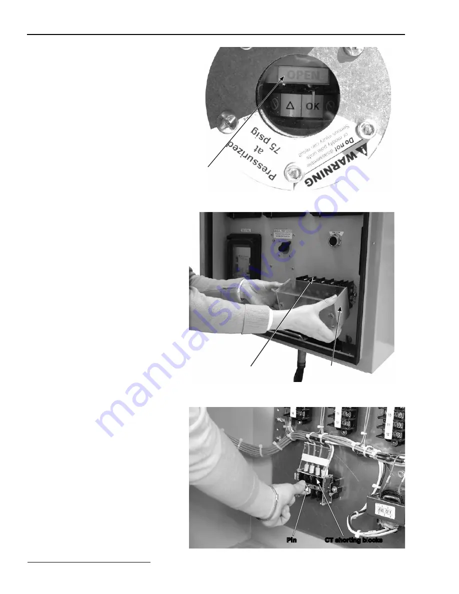
Figure 57. Check that each pole-unit position indicator shows “OPEN” 

and discharged. 

Step 50

To initiate a trip operation, inject secondary 
current into the relay. Refer to the relay manu-
facturer’s instructions.

Step 51

Verify that the pole-units operated properly. 
Check that each pole-unit position indicator 
shows “OPEN” and discharged. See Figure 57.

Step 52

To initiate a trip operation, inject secondary 
current into the relay. Refer to the relay manu-
facturer’s instructions.

To check operation of the trip-energy supply, 

inject single-phase secondary current above  
600 mA, but 

below

 the pick-up setting of 

the relays, into the trip-energy supply, with  
600 mA input current the trip-energy supply 
will charge in approximately 3 seconds. Use a 
user-furnished secondary current-injection kit 
as follows:
a. 

If an optional test switch is furnished,


remove the test-switch cover and inject sec-
ondary current in accordance with stan dard 
operating procedure. See Figure 58.

b. 

If the optional test switch is not fur-
nished,

 use the CT shorting blocks in the 

control cabinet to inject secondary current. 
Use the furnished pins to short the CTs, then 
inject secondary current, in accor dance  
with standard operating procedures. See 
Figure 59.

Control Cabinet Set-Up

Figure 58. Remove the test-switch cover and inject secondary current, in 

accordance with standard procedure.

Test switch

Cover

Figure 59. If optional test switch is not furnished, place pins in the CT 

shorting blocks.

Pin

CT shorting blocks

30  

S&C Instruction Sheet 731-502

Summary of Contents for Trans-Rupter II SE

Page 1: ...inet Set Up Connecting Current Transformers to the Control Cabinet 27 Testing Control Devices 28 Installing Optional Bypass Accessory Before Starting 32 Operation 33 Terminal Pad and Conductor Connect...

Page 2: ...CAUTION The equipment in this publication is only intended for primary side application on distribution substation transformers The application must be within the ratings fur nished for the equipment...

Page 3: ...NOTICE identifies important procedures or requirements that can result in product or property damage if instructions are not followed Following Safety Instructions If you do not understand any portio...

Page 4: ...afety Alert Message Description Part Number A WARNING Do not close Trans Rupter II if the source side series disconnect is closed G 7016R1 B WARNING Do not charge if disconnect is closed G 7009 1 C WA...

Page 5: ...three pole units a control cabinet a manual charging tool and six terminal pads and their associated hardware Pole units are shipped fully pressurized at 75 psig The pole units and charging tool are...

Page 6: ...rate and lift it using the following procedure CAUTION Lift the pole unit only by the lifting bracket Lifting it by any other means can dam age the pole unit Wrap a hoist sling or other lifting device...

Page 7: ...Installation on a User Furnished Structure Figure 2 Pull the pole unit carefully upward Figure 3 Do not remove the shipping brace at this time Pole unit Shipping brace S C Instruction Sheet 731 502 7...

Page 8: ...d the pole unit lifted off the ground check that the gas pressure gauge on the underside of the pole unit base is in the OK to operate zone See Figures 4 and 5 NOTICE The gas pressure gauge needle sho...

Page 9: ...can be mounted in one of four positions located 90 apart Determine where terminal pads will be attached before mounting the pole unit Step 5 Remove the shipping brace from the pole unit base See Figur...

Page 10: ...ling or lifting device from the pole unit at this time See Figure 8 Figure 8 Attach the pole unit base to the bracket Top and bottom mounting boss locations Mounting bracket Pole unit base Step 7 Atta...

Page 11: ...UTION Two sets of mounting bosses positioned 180 apart must be used to mount the pole unit If the correct mounting bosses are not used the pole unit will not be ade quately supported and the pole unit...

Page 12: ...Then bolt all four tabs to the mounting structure using user furnished C inch hardware See Figure 13 Figure 13 Bolt the tabs of the control cabinet to the mounting structure Mounting structure Top mo...

Page 13: ...her location Figure 16 Remove the three removable screws at each pole unit electrical junction box cover Loosen the fourth retaining screw Window bolts DO NOT REMOVE Retaining screw Cover Removable sc...

Page 14: ...hole s along the bottom of the con trol cabinet See Figure 18 Figure 18 Attach the conduit to the hole s along the bottom of the connection enclosure Conduit Step 17 Following the wiring diagram furn...

Page 15: ...for the connection enclosure face the desired direction per the catalog drawing b Adjust the lower set of anchor bolt nuts to generally plumb and level the pedestals The upper set of anchor bolt nuts...

Page 16: ...arm attachment brackets using the B 1131Z x bolts furnished Fully tighten the bolts e Using a level verify that the cross base is horizontal both lengthwise and side to side Adjust the anchor bolts as...

Page 17: ...fully pull the pole unit upward The foam wrappings around the top mid section and base should come off as the pole unit is lifted Remove these wrappings if they do not come off Do not remove the shipp...

Page 18: ...he pole unit lifted off the ground check that the gas pressure gauge on the underside of the pole unit base is in the OK to operate zone See Figures 29 and 30 NOTICE The gas pressure gauge needle shou...

Page 19: ...where the conduit will be attached See Figure 31 Step 30 Remove the shipping brace from the pole unit base See Figure 32 CAUTION DO NOT rest the pole unit on its base after the shipping brace has been...

Page 20: ...osses must be used Screw each stud until it bottoms approxi mately 8 to 9 turns DO NOT remove the hoist sling or lifting device from the pole unit at this time See Figure 34 Figure 33 Place the pole u...

Page 21: ...ng or lifting device from the pole unit Figure 35 Tighten the nuts Pole unit base Mounting bracket Cross base Pedestal Tabs Tabs Figure 36 Bolt the tabs of the control cabinet to the pedestal Mounting...

Page 22: ...onal area to the flange at the bottom rear of the enclosure Flange Base of control cabinet Figure 38 If additional holes for control wiring are required remove the conduit entrance plate and punch the...

Page 23: ...y in the hooks at the top of the pedestals Conduit assembly Pedestal hooks Figure 41 Using the offset mounting brackets attach the conduit assembly to the pedestal Offset mounting bracket Conduit asse...

Page 24: ...22 AWG wire Use of 18 gauge wiring is recommended NOTICE To ensure proper crimping of the butt splices use the Panduit controlled cycle hand tool CT 1550 or equivalent for attaching 18 to 20 gauge in...

Page 25: ...eyed to the female socket See Figure 45 Push the plug into the socket and turn the black ring until the red line around the outside of the socket is obscured See Figures 46 and 47 Figure 47 Quick conn...

Page 26: ...tep 47 Connect the pole unit wiring and user furnished control circuit wiring to the appropriate termi nation blocks in the control cabinet in accor dance with the wiring diagram furnished See Figure...

Page 27: ...protection system may not function properly Step 48 Following the wiring diagram furnished con nect user furnished current transformers CTs to the shorting blocks in the control cabinet Follow standar...

Page 28: ...Guide the hooked end of the charging tool between the ears of the pole unit operating shaft and engage the operating shaft pin See Figures 51 52 and 53 CAUTION Use only the manual charging tool provid...

Page 29: ...to reset the pole unit mechanism See Figure 55 Approxi mately 40 revolutions are needed Keep turning until the internal stop is reached Then remove the charging tool CAUTION The charging tool must be...

Page 30: ...600 mA input current the trip energy supply will charge in approximately 3 seconds Use a user furnished secondary current injection kit as follows a If an optional test switch is furnished remove the...

Page 31: ...rol Cabinet Set Up Step 53 To initiate a trip operation inject secondary current into the relay Refer to the relay manu facturer s instructions Verify that the trip energy supply is storing energy Ope...

Page 32: ...nduc tors terminal pads and associated hardware Step 54 Thoroughly clean the surface of the Trans Rupter II casting and the surface of the bypass accessory terminal pads using a soft cloth Immediately...

Page 33: ...nter line of the contact fingers See Figure 63 If the blade assembly needs adjustment loosen the hinge support and blade stop bracket hardware See Figure 64 Center the blade between upper contact fing...

Page 34: ...sing the Z x 1331 hex head stainless steel cap screws and Z x inch stainless steel lockwashers furnished attach the upper and lower terminal pad to the appropriate set of tapped holes on the pole unit...

Page 35: ...d in any posi tion Test for voltage using proper high voltage test equipment and install suitable grounding equipment Failure to observe these precautions may result in serious injury or death Repeat...

Page 36: ...e See Figure 69 The pins for CT shorting blocks are removed See Figure 70 Refer to the relay manufacturer s instruc tions for set up and testing procedures for the relays Figure 68 Make sure all three...

Page 37: ...and the insulated shaft Linchpin Figure 72 Pull the tool handle and the insulating shaft apart Linchpin Tool handle Insulating shaft NOTICE To prevent excessive wear or corrosion store the Trans Rupt...

Page 38: ...t Tool head Figure 75 Push the tool head and the insulating shaft together Assembling the Charging Tool Step 68 Push the tool head and the insulating shaft together Align the holes on the tool head an...

Page 39: ...s for the Charging Tool Extra sections can be assembled in accordance with the instructions above It is recommended that a maximum of two 48 inch sections be added to the tool Figure 77 Push the handl...

Page 40: ...the indicator reads CLOSED See Figure 80 CLOSED and charged Figure 80 The pole unit is CLOSED and charged The indicator reads CLOSED Figure 81 Gauge needle in white OK to operate zone OK to operate z...

Page 41: ...inimum functional level and the pole unit will not maintain full interrupting or dielectric ratings The pole unit should be removed from service and replaced promptly Do not operate this Trans Rupter...

Page 42: ...gas den sity in the pole unit has dropped below the minimum functional level The pole unit will not maintain full interrupting or dielectric ratings The pole unit should be removed from service and re...

Page 43: ...es Check that the red LED is flashing See Figure 86 That the trip energy supply is storing energy Open the swingout panel to access the cir cuit board of the trip energy supply Press the push button o...

Page 44: ...r s instruc tions for recommendations on testing and inspection of the relays Guidelines for Interrupter Resistance Values Trans Rupter II interrupters should have resis tance values under 200 micro o...

Reviews: