SRG-1150DN / SRG-1250DN / SN-100
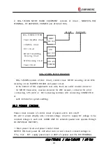
2. SRG- 1250DN MF/HF RADIO EQUIPMENT consists of circuit , NBDP(SN- 100)
TERMINAL, RF AMPLIFIER, PRINTER and ATU(SAT- 100).
RX ANT
TX/RX ANT
SRG- 1250DN SYSTEM
Power Amplifier Circuit
CONTROL Circuit
DSC C ircuit
MF/HF Transmitting,
Receiving Circuit
W/K Receiving Circuit
Power C ircuit
NBDP
SN- 100
W/K
ATU
SAT- 100
DPU- 414
PRINTER
SRG- 1250DN BLOCK DIAGRAM
SRG- 1250DN consists of DSC circuit, control circuit, MF/HF receiving circuit, W/K
receiving circuit, MOTHER BOARD and power circuit.
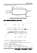
At the bottom of this equipment's rear side, there are aerial coaxial connector
for MF/HF transceiver, coaxial connector for W/K receiver, connector for print
connecting, SPK J ACK or BK Connecting terminal, ATU connecting CONNECTOR
or
earth terminal for system earthing.
10.2 POWER CIRCUIT
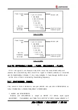
Power circuit consists of control circuit of power unit to turn on/off
DC- 24V in power amplify unit, constant voltage circuit to supply DC voltage to be
constant voltage in each unit, AUDIO AMP for external speaker and operate through
DC INPUT(24V BATTERY).
⑴ Main power circuit and power control circuit
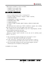
SWITCH ON main power DC 24V when turn on and convert constant voltage to
+15v, +12v . EXT. supply power even in AMP of speaker and SN- 100 TERMINAL.

