SRG-1150DN / SRG-1250DN / SN-100
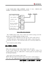
frequency multiplier circuit(T7, 9, 11, 12) and use as 2‘nd LOCAL.
3'th LOCAL makes 456.4KHZ± 125HZ signal directly from DDSI.
② W/K UNIT SYNTHESIZER
PLL(IC17)and VCO(VCO&) is output as MF/HF 1‘st LOCAL inputting signal
(66.2595MHZ, 62.0120MHZ, 57.8695MHZ, 55.7670MHZ, 53.6625MHZ, 51.6425MHZ)
In output of DDS3, outputting 7 MHz make 49MHz in 7 frequency multiplier
circuit(T8. 9. 11, 12) and use as 2‘ nd LOCAL.
3'th LOCAL makes 456.7KHZ signal directly from DDS1.
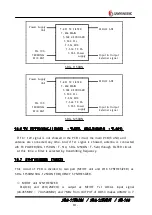
10.8 POWER CONTROL (T-555)
Circuit of this PCB have main constant voltage (+12V) and vertical current
CHECK circuit(IC2).
If PWR SW turn ON, relay do not operate until becoming 4.5V by IC7, this signal
make TX CURRENT happen through BiMOS Operational Amplifiers(IC3), AUDIO
signal(CONNECTOR 6PIN, 5PIN) connect PHONE J ACK through amplifier(IC6).
10.9 PA AMP(SRG-1150DN : T-514, SRG-1250DN : T-524)
This PCB circuit consists of TX output POWER AMP, TX output is
150W(SRG- 1150DN) and 250W(SRG- 1250DN).
10.10 CONTROL (T-557)
This PCB circuit consists of CPU(IC1), MEMORY ROM(IC2)/RAM(IC3), CLOCK
GENERATOR(IC4), BUFFER(IC5), I/O AMPLIFY(IC17), AC/DC CONVERTER(IC15),
RS- 232C(IC13), DECODE COUNTER(IC28) for convert 10MHZ to 1MHZ,
EEPROM(IC12), FS MOD EM(M2), DDS(M1), AUDIO AMPLIFIER(IC20),
MUX/DEMUX(IC24) for controlling LCD CONTRAST.
And it controls SRG- 1150DN/SRG- 1250DN on the whole, such as operation of
TX/RX, switch, front LCD and etc.
Control unit has function to make signal to need in controling of synthesizer part
had a outbreak according to PANEL operating of control unit, function of
information- exchange and function of indication- control.
It is composed of MICRO COMPUTER of 16Bit.


