background image

Samsung Electronics

4-13

Troubleshooting

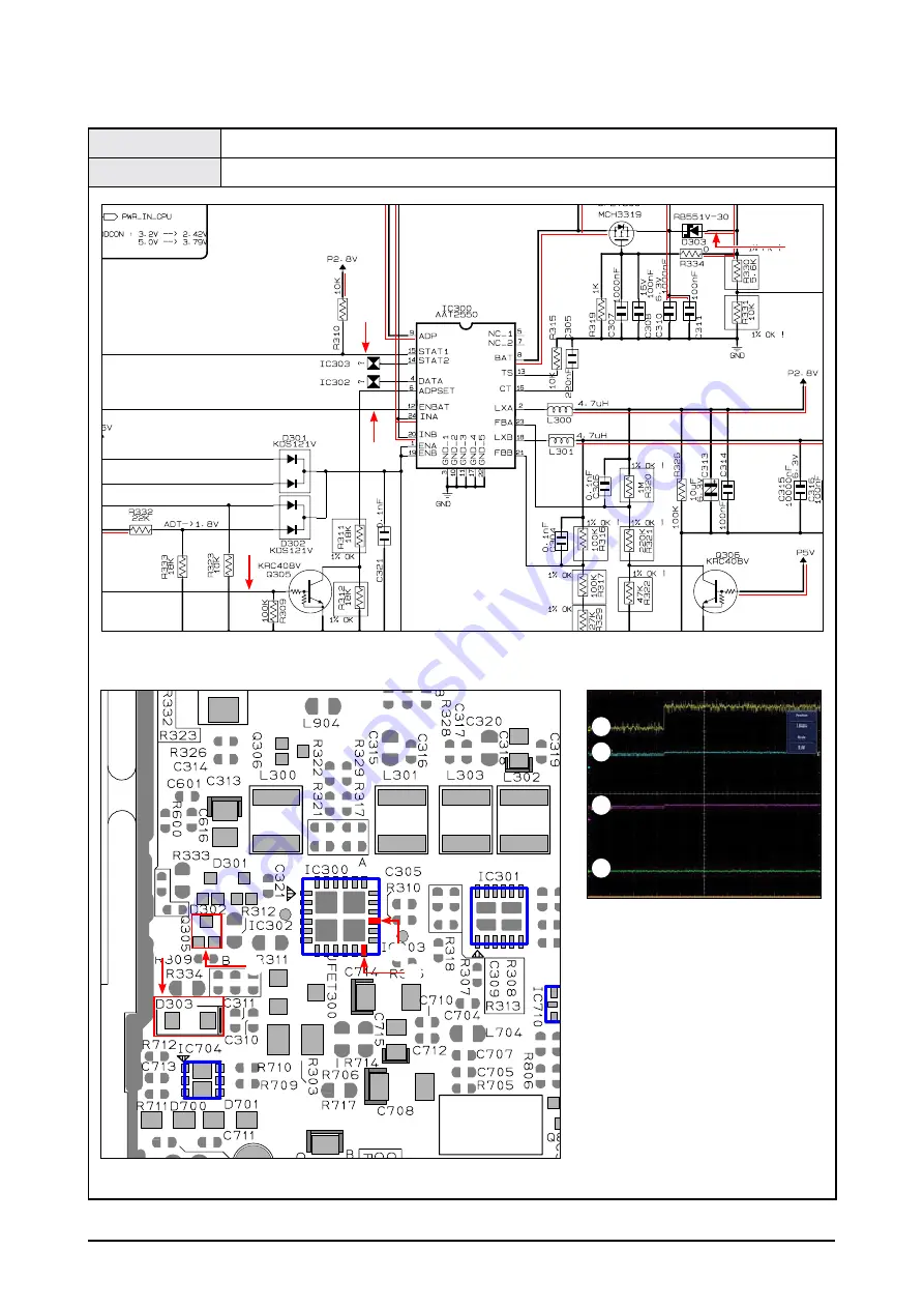
Test Point

D303, IC300 15PIN, IC300 12PIN, Q305

Result

D303 → 5V, IC300 15/12PIN → HIGH, Q305 → HIGH: ADAPTER, LOW: USB

 POWER Management Page, 7-3

CON803

IC300

IC704

IC710

IC403

IC301

 PCB Bottom Page, 6-3

<Table 4-6>

2

1

3

4

1

3

2

2

3

4

1

4

Summary of Contents for YP-P2

Page 1: ...O YP P2JQW XEO YEPP Refer to the service manual in the GSPN see the rear cover for the more information CONTENTS 1 Precaution 2 Product Specification 3 Disassembly Reassembly 4 Troubleshooting 5 Explo...

Page 2: ...domestic law GSPN Global Service Partner Network Area Web Site North America service samsungportal com Latin America latin samsungportal com CIS cis samsungportal com Europe europe samsungportal com...

Page 3: ...1 4 Troubleshooting 4 1 Checkpoints by Error Mode 4 1 4 2 Upgrade Methods 4 16 5 Exploded View Part List 5 1 Exploded View 5 1 5 2 Electrical Part List 5 3 6 PCB Diagram 6 1 PCB Top 6 1 6 2 PCB Botto...

Page 4: ...tical damage 3 You should not use this product near water such as bathtub swimming pool or lake etc 4 Power supply A type of battery as displayed on the label should be only used 5 You should not put...

Page 5: ...or or devices with elements for semi conductor You should purchase and use static electricity arm rings or commercially available You should remove it due to potential shock before supplying power to...

Page 6: ...named EmoTrueTM UI User Interface that allows to operate sensually all functions by using touch Icons on screen without uncomfortable buttons press High Resolution 3 WIDE QVGA 480x272 LCD that allows...

Page 7: ...atio 59dB FM Distortion 0 8 FM Effective Sensitivity 5dBu Battery Type Li Polymer Rechargeable Battery Built in Rechargeable Battery Capacity 830 mAh Playback Time 35 Hours of Music Playback Based on...

Page 8: ...hargeable Battery Built in Re chargeable Battery Capacity 830 mAh Li Polymer Rechargeable Battery Built in Re chargeable Battery Capacity 830 mAh Color White Black Red Wine Silver Black Files MP3 WMA...

Page 9: ...roduct Specification 2 4 Accessories 2 4 1 Supplied Accessories Accessories Item Item code Remark Earphones Black AH30 00087E Samsung Service center White AH30 00086H USB Cable AH39 00899A Program Ins...

Page 10: ...vulnerable to static electricity Assemble in the reverse order of disassembly No Part Name Description Description Photo 1 CABINET BACK 1 After removing the Serial Label at bottom remove the screw M1...

Page 11: ...ews holding the PCB in place M1 7 L3 HEAD3 0 TAPTITE 2 Remove the BATTERY after lifting up the PCB from the CABINET FRONT by using a pair of tweezers Be sure to observe BATTERY polarity when re connec...

Page 12: ...RY effect from double coated tape Re attach a new double coated tape after removing an old thing when assembling a BATTERY Capadty 830mAh Nominal Vottage 3 7V CAUTION Danger of exploslon if battery is...

Page 13: ...FRONT from the HOLDER FRAME The CABINET FRONT is attached to the HOLDER FRAME by a double coated tape Be careful not to make any scratches as you remove it 2 USE a pair of tweezers to remove CUSHION...

Page 14: ...s HIGH when the POWER key is pressed 2 5V 3 1V 3 Check if the ENABLE pin signal of the DDCON IC is HIGH 2 5V 3 1V 4 Check power L300 2 8V MAIN L301 1 07V CORE L302 1 8V MEMORY L303 3 1V LCD Caution Be...

Page 15: ...CD Yes No Check BATTERY power IC803 IC804 Check MAIN 12Mhz clock No Defective Yes Yes No No No A Refer to wave pattern image of Table 4 1 Refer to wave pattern image of Table 4 1 Completion 3 Check DD...

Page 16: ...C300 1PIN 19PIN IC301 1PIN 4PIN L300 L301 L303 L302 Result Check for HIGH input POWER Management Page 7 3 POWER Management Page 7 3 CON803 IC300 IC704 IC710 IC403 IC301 PCB Bottom Page 6 3 Table 4 1 2...

Page 17: ...ses Are the skips and noises even when playing another file Does the same symptom persist even after upgrading the firmware to the latest version Yes No Yes Yes Yes Yes Yes Does the same symptom persi...

Page 18: ...ectronics 4 5 Troubleshooting Test Point C714 3 1V C705 2 8V L704 1 8V Result Check each output terminal Audio CODEC Page 7 7 CON803 IC300 IC704 IC710 IC403 IC301 PCB Bottom Page 6 3 Table 4 2 2 1 3 2...

Page 19: ...D Is TOUCH KEY reaction Check the top of the unit to see if it is set to HOLD SW ON 2 Disassemble the unit and check if TOUCH FPCB is defective If the TOUCH is poor replace the TOUCH PAD Yes No Yes No...

Page 20: ...Samsung Electronics 4 7 Troubleshooting Test Point C810 2 8V Result Check the output terminal 24PIN IO Interface Page 7 8 CON803 IC710 IC403 IC301 PCB Bottom Page 6 3 Table 4 3 1 1 1...

Page 21: ...wer C107 1 0V Completion Yes Yes No Is RTC CLOCK functioning normally Check the DIVIDE resistance R525 220K R526 1M 2 Wave pattern Peak Peak 1 8V Check Are the earphones plugged in Yes No Reactivate a...

Page 22: ...tronics 4 9 Troubleshooting Test Point C107 R526 Result C107 1 0V R526 32 768KHz BLUETOOTH FM Page 7 10 TCC7801 I O Setting Reset Page 7 5 CON803 IC300 IC710 IC403 IC301 PCB Bottom Page 6 3 Table 4 4...

Page 23: ...Check the CON900 LCD B to B connector Q300 LCD_DRV signal No No Check the DC DC converter No Check the LCD reset signal of the CPU Completion Yes Yes Yes 2 Check if the voltage at L900 is 3 1V 1 Chec...

Page 24: ...ubleshooting Test Point D900 13V L900 3 1V R908 2 8V Result Check the output terminal WQVGA LCD Interface Page 7 9 CON900 IC703 IC600 IC700 PCB Top Page 6 1 IC300 IC704 IC710 IC301 PCB Bottom Page 6 3...

Page 25: ...GING 4 Check CHRG_CTL Q305 HIGH USB LOW ADAPTER Check the adapter and the PC No No Make a precision measurement of IC300 AAT2550 LOW LOW USB charging HIGH Adapter charging Yes Yes HIGH 2 3 Check for t...

Page 26: ...shooting Test Point D303 IC300 15PIN IC300 12PIN Q305 Result D303 5V IC300 15 12PIN HIGH Q305 HIGH ADAPTER LOW USB POWER Management Page 7 3 CON803 IC300 IC704 IC710 IC403 IC301 PCB Bottom Page 6 3 Ta...

Page 27: ...Yes Yes No No Yes No No Defective Yes Yes No No Poor PC Connection Plug the device into the USB port 2 Check if the EXT_PWR External Power R522 signal is maintained at HIGH level 1 Is 12MHz CLOCK fun...

Page 28: ...ung Electronics 4 15 Troubleshooting Test Point R527 R522 Result R527 Freq 12Mhz Peak Peak 3V R522 3V TCC7801 I O Setting Reset Page 7 5 CON803 IC710 IC403 IC301 PCB Bottom Page 6 3 Table 4 7 1 2 2 1...

Page 29: ...d 1 Download the firmware upgrade file to a folder and decompress it 2 Check the contents of the folder that was decompressed 3 Connect the YP P2 to the PC 4 Open the Removable Disk folder of the YP P...

Page 30: ...y connect the device to the USB port When RESET is pressed it will be connected in FWDN Mode Once the FWDN connection is established you may release the POWER key 2 The device should be installed afte...

Page 31: ...msung Electronics Troubleshooting 3 Browse to the FWDN Driver directory and select the vtcdrv sys file 4 Click Continue to continue the driver installation 5 Click Finish to complete the driver instal...

Page 32: ...Samsung Electronics 4 19 Troubleshooting 3 Execute the FWDN exe file 1 Select the ROM file to be restored 2 Finish uploading to SDRAM Connect the device to the USB port...

Page 33: ...4 20 Samsung Electronics Troubleshooting 3 Click on the WRITE button 4 Confirm the Writing Complete message ROM File WRITING...

Page 34: ...e and check the MAC Address sticker inside 2 Enter the following MAC Address in a blank text file and save it with the name shown below 3 Establish the USB connection and copy and paste the file to th...

Page 35: ...onics Exploded View Part List This Document can not be used without Samsung s authorization 5 Exploded View Part List 5 1 Exploded View AC010 AC357 AK200 AH228 AK420 AL093 AR061 A B AA001 AC115 AT300...

Page 36: ...6 W45 1 L77 8 1 SA QW AH228 AH61 02382A HOLDER FRAME YP P2 PPA GF50 T1 2 W50 L9 1 SNA CB AH61 02382B HOLDER FRAME YP P2 PPA GF50 T1 2 W50 L99 WHIT 1 SNA QW AK200 AH64 04318A KNOB HOLD YP P2 PC T1 2 W2...

Page 37: ...80 20 10V Y5V 1 1 SA C405 2203 002709 C CER CHIP 100nF 80 20 16V Y5V 10 1 SA C406 2203 002709 C CER CHIP 100nF 80 20 16V Y5V 10 1 SA C407 2203 005900 C CER CHIP 1000NF 80 20 10V Y5V 1 1 SA C414 2203 0...

Page 38: ...128 DIODE TVS MLVS 0603 E08 50V 1 SA D900 0402 001075 DIODE RECTIFIER MBR0520L 20V 0 5A S 1 SA IC100 1205 003216 IC TRANSCEIVER BCM2048SKUFBG UFBGA 1 SA IC101 AH61 02433A SUPPORT PCB YP P2 Cu T1 7 W2...

Page 39: ...5 2007 000148 R CHIP 10Kohm 5 1 16W TP 1005 1 SA R516 2007 000148 R CHIP 10Kohm 5 1 16W TP 1005 1 SA R517 2007 000148 R CHIP 10Kohm 5 1 16W TP 1005 1 SA R518 2007 000140 R CHIP 1Kohm 5 1 16W TP 1005 1...

Page 40: ...TRATION HUNGARY SEH HUNGA 1 SNA AH30 00087E PHONE EARPHONE BUSHING Black 32 1 1 SA AH39 00899A CBF CABLE USB CABLE 49338 0001 YP T 1 SA AH46 00050A S W CD INSTALL CD YP P2 YP P2 INSTA 1 SA AH63 01482A...

Page 41: ...5 7 Samsung Electronics MEMO...

Page 42: ...759B AH92 02759C AH92 02759D A S Code AH82 00149A AH82 00149C AH82 00149E AH82 00149G RCL Existing AH92 02759A AH92 02759B A S Code AH82 00149A AH82 00149C AH82 00149E AH82 00149G SMT Existing AH92 02...

Page 43: ...02759B AH92 02759C AH92 02759D A S Code AH82 00149A AH82 00149C AH82 00149E AH82 00149G XSP Existing AH92 02759A AH92 02759B AH92 02759C A S Code AH82 00149A AH82 00149C AH82 00149E AH82 00149G XSV E...

Page 44: ...Existing A S Code SUN Existing A S Code SKD Existing AH92 02759A A S Code AH82 00149B AH82 00149D AH82 00149F AH82 00149H TSE Existing A S Code XAA Existing AH92 02759B AH92 02759C AH92 02759D A S Co...

Page 45: ...00149H XER Existing A S Code XET Existing AH92 02759A AH92 02759B AH92 02759C A S Code AH82 00149B AH82 00149D AH82 00149F AH82 00149H XEU Existing AH92 02759A AH92 02759B AH92 02759C AH92 02759D A S...

Page 46: ...8 0 4 2 6 9 7 1 HOLD KEY 2 SDRAM 32MB 3 POWER KEY 4 MPU 5 TSP Connector 6 USB Connector 24PIN 7 EARPHONE JACK 8 BLUETOOTH ANT 9 BLUETOOTH FM 0 NAND Flash 26MHz VOLUME UP DOWN KEY LCD Connector TP10 T...

Page 47: ...NT 21 BATT DC4 2V 10 USB D 22 BATT DC4 2V 11 N C 23 EXT_BAT_DET 12 GND 24 PBA_CE 7 EARPHONE JACK Pin No Signal 1 GROUND 2 R CH 3 L CH LCD Connector Pin No Signal Pin No Signal Pin No Signal 1 VDD2 39...

Page 48: ...TP2 TP1 3 8 7 5 4 1 TP17 TP16 TP4 TP5 TP18 2 TP15 TP3 TP6 TP7 TP13 TP9 TP8 TP12 TP14 1 DDCON 2 Charger DDCON 3 MIC 4 RST IC 5 32 768KHz 6 MAIN 12MHz 7 Debugging Connector 8 BATTERY TP TP24 TP21 TP20...

Page 49: ...V 2 JTAG_RTCK 3 JTAG_TCK 4 JTAG_TDO 5 JTAG_TMS 6 JTAG_TDI 7 JTAG_RST 8 GND 9 UART_TX1 10 UART_RX1 11 DEBUG_PWR_ON 12 V_DDCON TP4 TP5 TP6 TP7 TP5 TP4 TP6 TP7 TP8 TP9 TP8 TP9 TP12 TP12 TP13 TP14 TP13 TP...

Page 50: ...ng s authorization 7 Schematic Diagram 7 1 Overall Block Diagram 7 2 7 2 Power Management 7 3 7 3 TCC7801 Power_Block 7 4 7 4 TCC7801 I O Setting Reset 7 5 7 5 Memory SDRAM NAND Flash 7 6 7 6 Audio CO...

Page 51: ...CM2048 SKUFBG 26MHz MAIN CLK B T ANT I2C I2S GPIO UART 1 2V 2 8V LITHUM BATTERY 3 7V_950mA 24pin connector External Battery Pack Alkaline 3pcs 24pin connector P5V OR USB P5V The Main System consists o...

Page 52: ...gram This Document can not be used without Samsung s authorization 7 2 Power Management TP1 TP2 TP3 TP4 TP5 TP6 TP7 TP15 TP16 TP17 TP18 TP2 TP1 TP3 TP5 TP4 TP6 TP7 TP16 TP15 TP17 TP18 POWER TP1 TP5 TP...

Page 53: ...7 4 Samsung Electronics Schematic Diagram This Document can not be used without Samsung s authorization 7 3 TCC7801 Power_Block POWER...

Page 54: ...ung Electronics 7 5 Schematic Diagram This Document can not be used without Samsung s authorization 7 4 TCC7801 I O Setting Reset TP8 TP9 TP8 TP9 TP13 TP13 POWER TP23 TP23 TP24 TP24 TP13 TP9 TP8 TP23...

Page 55: ...7 6 Samsung Electronics Schematic Diagram This Document can not be used without Samsung s authorization 7 5 Memory SDRAM NAND Flash POWER...

Page 56: ...Samsung Electronics 7 7 Schematic Diagram This Document can not be used without Samsung s authorization 7 6 Audio CODEC POWER AUDIO TP19 TP19 TP20 TP20 TP21 TP21 TP19 TP20 TP21...

Page 57: ...7 8 Samsung Electronics Schematic Diagram This Document can not be used without Samsung s authorization 7 7 24PIN I O Interface POWER TP22 TP22 TP22...

Page 58: ...Samsung Electronics 7 9 Schematic Diagram This Document can not be used without Samsung s authorization 7 8 WQVGA LCD Interface TP10 TP11 TP12 TP10 TP11 TP12 POWER TP11 TP12 TP10...

Page 59: ...7 10 Samsung Electronics Schematic Diagram This Document can not be used without Samsung s authorization 7 9 BLUETOOTH FM TP14 TP14 POWER TP14...

Reviews: