6-1
6. PCB Diagram
6. PCB Diagram
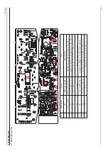
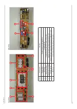
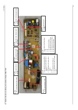
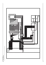
6-1. Main PCB / Sub PCB
Part
Part Number
Function
Role
1
R
Y1
PBA
Power Supply
,QSXW
$&9
2
TRAIC1,
TRAIC2
W
ashing Motor Drive IC
Switches and supplies the voltage to the motor
.
3
CN3
AC CONNECT
OR
Supplies the power from the power cord to the PBA.
4
CN8
AC CONNECT
OR
The connector for the
AG operating control.
5
CN4
FLASH
For MICOM R/W communication
6
CN1
AC CONNECT
OR
Supplies the voltage for the Silver Nano operation.
7
&1
Drive Block Connector
7KHFRQQHFWRUIRUWKH9
DOYH'UDLQRSHUDWLQJFRQWURO
8
DSP1
DISPLA
Y
Displays functions and operations.
8
4
5
1
3
2
2
11
6
7
Summary of Contents for WA10VP
Page 25: ...3 12 3 Disassembly and Reassembly Memo ...
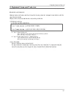
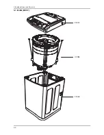
Page 27: ...5 2 SORGHG 9LHZV DQG 3DUWV LVW 5 1 MAIN BEST P0001 U0084 F0062 ...
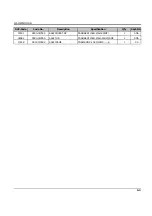
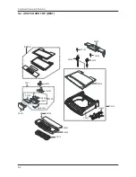
Page 31: ...5 6 5 3 ASSY TUB 262 9 4 ...
Page 38: ...6 4 6 PCB Diagram Memo ...
Page 40: ...7 2 UG Gk Mome ...
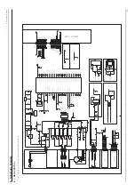
Page 41: ...8 1 _UGz Gk 1 Vfkhpdwlf Gldjudp 041 PDLQ FRQWURO G Gk G G G G G Gz G U ...
Page 42: ...8 2 _UGz Gk 051 VXE FRQWURO G Gk G G G G G Gz G U ...

