3-4
3. Disassembly and Reassembly
3-3. Standard Disassembly Procedures
¿
This is a standard disassembly diagram and may differ from the actual product.
Use this material as a reference when disassembling and reassembling the product.
Part Name
Disassembly Picture
Description
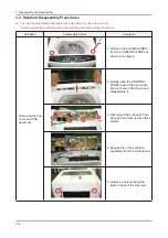
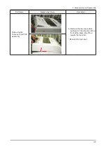
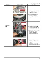
Removing the Top-
cover and PCB
assembly
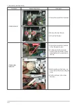
1. Remove the COVER-SCREW-
from the CONTROL-PANEL as
VKRZQLQWKH¿JXUH
2. Quietly raise the CONTROL-
PANEL toward the arrow direc-
WLRQDVVKRZQLQWKH¿JXUHDQG
disassemble it.
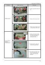
3. Disconnect the connector from
Assy-pcb and then remove the 4
screws.
4. Assy-pcb is in the condition
separated from the controlpanel.
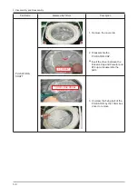
5HPRYHVFUHZV¿[LQJWKH
parts in back of the top-cover.
Summary of Contents for WA10VP
Page 25: ...3 12 3 Disassembly and Reassembly Memo ...
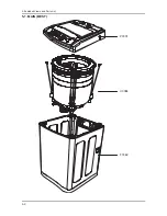
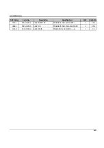
Page 27: ...5 2 SORGHG 9LHZV DQG 3DUWV LVW 5 1 MAIN BEST P0001 U0084 F0062 ...
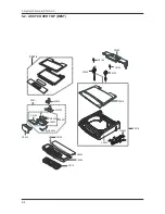
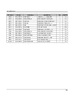
Page 31: ...5 6 5 3 ASSY TUB 262 9 4 ...
Page 38: ...6 4 6 PCB Diagram Memo ...
Page 40: ...7 2 UG Gk Mome ...
Page 41: ...8 1 _UGz Gk 1 Vfkhpdwlf Gldjudp 041 PDLQ FRQWURO G Gk G G G G G Gz G U ...
Page 42: ...8 2 _UGz Gk 051 VXE FRQWURO G Gk G G G G G Gz G U ...

