background image

Contents

1. Safety Instructions.................................................................................................................1-1

1-1. Safety Instructions for Service Engineers.......................................................................................................1-1

)HDWXUHVDQG6SHFL¿FDWLRQV

..................................................................................................2-1

2-1. Features .........................................................................................................................................................2-1

6SHFL¿FDWLRQV

.................................................................................................................................................2-3

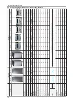
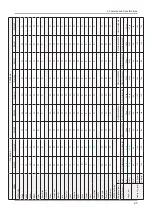
&RPSDULQJ6SHFL¿FDWLRQVZLWK([LVWLQJ0RGHOV

.............................................................................................2-4

2SWLRQV6SHFL¿FDWLRQV

..................................................................................................................................2-6

3. Disassembly and Reassembly ..............................................................................................3-1

3-1. Tools for Disassembly and Reassembly.........................................................................................................3-1

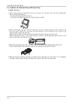
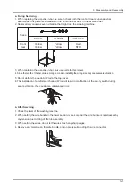
3-2. Cautions for Disassembly and Reassembly ...................................................................................................3-2

3-3. Standard Disassembly Procedures ................................................................................................................3-4

3-4.

6SLQ1XW5HSDLULQJ%R[

.............................................................................................................................. 3-11

4. Troubleshooting.....................................................................................................................4-1

4-1. Error Modes....................................................................................................................................................4-1

4-2. Corrective Actions for Each Error Code..........................................................................................................4-6

([SORGHG9LHZVDQG3DUWV/LVW

..............................................................................................5-1

5-1. MAIN (BEST)..................................................................................................................................................5-2

$66<&29(5723%(67

...........................................................................................................................5-4

5-3. ASSY TUB&DRUM (BEST) ............................................................................................................................5-6

5-4. ASSY PAINT / ASSY BASE / ASSY CASE (BEST) ........................................................................................5-8

5-5. PARTS LIST (SCREW TYPE) (BEST)..........................................................................................................5-10

6. PCB Diagram.........................................................................................................................6-1

6-1. Main PCB / Sub PCB......................................................................................................................................6-1

6-2. Detailed Connector and Relay Terminal Block Manual (Main PCB)...............................................................6-3

7. Wiring Diagram......................................................................................................................7-1

7-1. Wiring Diagram...............................................................................................................................................7-1

8. Schematic Diagram ...............................................................................................................8-1

8-1. MAIN CONTROL ............................................................................................................................................8-1

8-2. SUB CONTROL..............................................................................................................................................8-2

Summary of Contents for WA10VP

Page 1: ...ual WASHING MACHINE FULLY AUTOMATIC CONTENTS WA11VP Refer to the service manual in the GSPN see the rear cover for the more information Safety Instructions HDWXUHV DQG 6SHFL FDWLRQV Removal and Reassembly Troubleshooting Exploded Views and Parts List PCB Diagram Wiring Diagram Schematic Diagram 1 2 3 4 5 6 7 8 ...

Page 2: ...3 Standard Disassembly Procedures 3 4 3 4 6SLQ 1XW 5HSDLULQJ R 3 11 4 Troubleshooting 4 1 4 1 Error Modes 4 1 4 2 Corrective Actions for Each Error Code 4 6 SORGHG 9LHZV DQG 3DUWV LVW 5 1 5 1 MAIN BEST 5 2 66 29 5 723 67 5 4 5 3 ASSY TUB DRUM BEST 5 6 5 4 ASSY PAINT ASSY BASE ASSY CASE BEST 5 8 5 5 PARTS LIST SCREW TYPE BEST 5 10 6 PCB Diagram 6 1 6 1 Main PCB Sub PCB 6 1 6 2 Detailed Connector an...

Page 3: ...ual can be punished under applicable International and or domestic law GSPN Global Service Partner Network Area Web Site North America http service samsungportal com Latin America http latin samsungportal com CIS http cis samsungportal com Europe http europe samsungportal com China http china samsungportal com Asia http asia samsungportal com Mideast Africa http mea samsungportal com ...

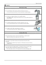
Page 4: ...es Make sure to disconnect the power plug before servicing Failing to do so may result in a risk of electric shock ࣃ Do not allow consumers to connect several appliances to a single power outlet at the same time 7KHUH LV D ULVN RI UH GXH WR RYHUKHDWLQJ ࣃ When removing the power cord make sure to hold the power plug when pulling the plug from the outlet DLOLQJ WR GR VR PD GDPDJH WKH SOXJ DQG UHVXOW...

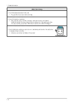
Page 5: ...ned part of the electrical harness ࣃ Check for any water leakage Perform a test run for the washing machine using the standard course and check ZKHWKHU WKHUH LV DQ ZDWHU OHDNDJH WKURXJK WKH ÀRRU VHFWLRQ RU WKH SLSHV ࣃ Do not allow consumers to repair or service any part of the washing machine themselves This may result in personal injury and shorten the product lifetime ࣃ If it seems that groundin...

Page 6: ...LPH ࣃ Do not press a control button using a sharp tool or object This may result in electric shock or damage to the product ࣃ During Servicing When wiring a harness make sure to seal it completely so no liquid can enter 0DNH VXUH WKDW WKH GR QRW EUHDN ZKHQ IRUFH LV H HUWHG ࣃ Check if there is any residue that shows that liquid entered the electric parts or harnesses If any liquid has entered into ...

Page 7: ...power cord from the power outlet and measure the insulation resistance between the power plug and the grounding wire of the washing machine 7KH YDOXH PXVW EH JUHDWHU WKDQ 0 ZKHQ PHDVXUHG ZLWK D 9 0HJJHU ࣃ KHFN ZKHWKHU WKH ZDVKLQJ PDFKLQH LV OHYHO LQ UHODWLRQVKLS ZLWK WKH ÀRRU KHFN ZKHWKHU LW LV LQVWDOOHG UPO RQ WKH ÀRRU 9LEUDWLRQV FDQ VKRUWHQ WKH OLIHWLPH RI WKH SURGXFW ࣃ ...

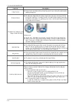
Page 8: ...Mist Shower 3嗛 Conventional Samsung Mist ShowerTM 88嗛 Ź Effective residue removal The mist dissolves laundry detergents more effectively to leave behind less resi due Ź 20 Water Savings A fine mist of water spray over the laundry reduces the amount of water necessary Air Turbo Drying System Ź Air Turbo technology spins hard and fast so you can spend less time drying Ź Time Saving AIR TURBO saves y...

Page 9: ...HU WKH ZDWHU surface It is this Waterfall Flow that enables this washing machine to effectively wash large and heavy items such as bluejeans and blankets Magic Filter Ź This unique magic Filter ensures that all the lint inside the tub is captured for top TXDOLW OWHULQJ UHVXOWV WR GHOLYHU FRQVLVWHQWO HIIHFWLYH FOHDQLQJ UHVXOWV Auto Restart Ź The power is turned on automatically after power failure ...

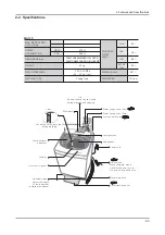
Page 10: ... G m G G w h G h G G G G G G G G G U m G G s i G G G G G G G G G G U z G s G G G G G G G G U m 0 0 66 2 5 27 1 NJ 67 1 5 7 5 9 83 M 32 5 2168037 21 6 470 0 76 M 63 1 280 0 16 216 PP W601XD654XH968 2 6 W601XD654XH993 HIGH BASE 2 55 M 7 41 NJ 75 2 43 M 7 5 35 6685 a 03D a NJ I FP 7 5 86 227 M 6 1 7 3 6WLUULQJ 7 SH 63 1 63 USP WA13P ...

Page 11: ...EOH VWRUP Silver Wash O X O O O O X X X 0LVW 6KRZHU O X O O X X X X X LU 7XUER U LQJ 6 VWHP O O O O O O O O O 6WDLQOHVV 6WHHO 7XE O O O O O O O O O 7UDQVSDUHQW LQGRZ O O O O O O O O O GMXVWDEOH HJ O O O O O O O O O Digital Display O O O O O O O O O LJLWDO X RJLF RQWUROV O O O O O O O O O RXUVHV 8 8 8 8 8 8 8 O 6 RORU 7RS FRYHU Dark Silver DULEEHDQ VLOYHU 0LVW EOXH 3LQN RSSHU 5H QHG ODFN 6LOYHU 1XG...

Page 12: ... X O O O O O O O Quick O O O O O O O O O Delicates X X O O O O O O O EASY O O O O O O O O X Soak X X X X X X X X O Speedy X X X X X X X X X Wool O O X X X X X X X Silver Wash O O O O O O X X X SAFETY Child Lock O O O O O O O O O Delay Start O O O O O O O O O Auto Restart O O O O O O O O O SPECIFICATIONS Dimensions mm Low PP High Weight kg Net 41 kg 41 kg NJ NJ NJ NJ NJ NJ NJ Gross 46 kg 46 kg 43 k...

Page 13: ... 1 1 0M COLD ASSY HOSE DRAIN DC97 09447A 1 Default MANUAL BOOK DC68 02597F 1 Default ASSY WIRE EARTH ASSY SHUTTER Note You can purchase additional water supply and drain hoses from a service center DC62 10290B HOSE WATER 1 1 0M HOT DC62 10289B ...

Page 14: ...Balance 5 2 on both sides of the shock absorber 1 Pulley Hole Damper oil 2 Damper rubbing 1 2 Double ended spanner 10mm 13mm PP 7KLV FDQ EH XVHG LQVWHDG RI WKH ER GULYHUV Leg 3 9LFH SOLHUV This is a tool that prevents the bolt from rotating idly or FDXVLQJ DEUDVLRQV ZKHQ XVLQJ ER GULYHUV Spin Drum Separation 4 JIG for the ASSY SPIN BASKET 5 Others Driver Nippers Long Nose General After Service Too...

Page 15: ...it in the direction of the front at the same time lift up quietly the rear side DXWLRQ KHQ RX GR QRW UHPRYH OLNH WKDW LQJ KRRNV HDV WR EUHDN LQ WKH IURQW VLGH KHQ UHPRYLQJ WKH FRYHU W F IURP WKH WRS FRYHU UHPRYH VFUHZV IL LQJ WKH SDUWV LQ EDFN RI WKH top cover and touch up softly with hands 3 When removing the top cover from the outer case do not let the wire bundle fall downwards and touch the sh...

Page 16: ...length of the bar varies among on models installing the wrong size may cause severe vibration 5 Do not deform the check S W rod of the top cover 6 The installation of a deformed check S W rod will result in malfunction of the safety switch during severe vibration thus causing an unbalanced error Ź After Servicing 1 Check the level of the washing machine 2 When setting the wire bundle in the lower ...

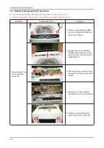
Page 17: ... Name Disassembly Picture Description Removing the Top cover and PCB assembly 1 Remove the COVER SCREW from the CONTROL PANEL as VKRZQ LQ WKH JXUH 2 Quietly raise the CONTROL PANEL toward the arrow direc WLRQ DV VKRZQ LQ WKH JXUH DQG disassemble it 3 Disconnect the connector from Assy pcb and then remove the 4 screws 4 Assy pcb is in the condition separated from the controlpanel 5HPRYH VFUHZV LQJ ...

Page 18: ...ssembly Part Name Disassembly Picture Description Removing the Topcover and PCB assembly 6 Remove the top cover while pushing it in the direction of the front at the same time lift up quietly the rear side Reverse the top cover ...

Page 19: ... two Screws 3 Lift out the Checker PRESSURE SENSOR HOOK 1 Pull out the Lead Wire Terminal of the Pressure Sensor 2 To disassemble the pressure sensor push the hooks on both sides slightly to the outer side to lift it up 3 Before pulling out the hose you must remove the clip by using the tools 4 Pull the air hose in the arrow direction ...

Page 20: ...o 2 screws 3 Remove the two water valves in the direction of the arrow BODY DETER GENT ASSY NOZZLE 1 Remove the terminals and then remove the top cover and body detergent by pushing the hook 2 Remove the 1 screw and remove the guide water 3 Push the assy nozzle in the direction of the arrow and remove it from the body detergent HOOK ...

Page 21: ... Description PULSATOR SHAFT 1 Remove the cover tub 2 Disassemble the PULSATOR CAP GInsert the driver between the Pulsator Cap and Pulsator and lift it up to disassemble the parts 8QVFUHZ WKH LQJ EROW RI WKH 38 6 725 E WKH PP ER driver to remove driver PP ER GULYHU ...

Page 22: ...eft counterclockwise Fastening direction of nut Right clockwise 5 Lay down the OUT CASE DQG XQVFUHZ IRXU EROWV LQJ WKH 6 ZLWK PP ER driver G When laying down the washing PDFKLQH RQ WKH ÀRRU EH careful of damaging or scratching of the product 5HPRYH IRXU EROWV LQJ WKH 6 7 ZLWK PP ER GULYHU and disassemble the SHAFT ASS Y Check the condition of the 6 7 DV VKRZQ DW WKH JXUH 10mm ER GULYHU 10mm ER GUL...

Page 23: ...tom may occur during the washing operation 2 Check if the TOOTH is separated from the end of the wings of the Sleeve by at least 1 0 mm during the K GURH WUDFWLRQ RSHUDWLRQ KHQ WKH Drain Motor is off If the separation distance is too short noise and binding symptoms PD RFFXU GXULQJ WKH K GURH WUDFWLRQ operation ASSY MOTOR 1 Pull the Assy Motor Housing to separate it 2 Remove the 4 bolts holding th...

Page 24: ...rt the connecting rod 嚀 and handle 嚁 LQWR WKH VTXDUH ER 7KHQ WXUQ WKH KDQGOH FORFNZLVH RQ WKH D LV RI WKH VPDOO ER WR GLVDVVHPEOH 5LJKW KDQG WKUHDG LOCK LOOSEN 7R GLVDVVHPEOH WKH ER JLYH WKUHH WR IRXU WLPHV RI LQVWDQWDQHRXV VKRFNV WR WKH KDQGOH LQ WKH ORRVHQLQJ GLUHFWLRQ then disassemble it by turning the handle when the nut is loosened 7R GLVDVVHPEOH WKH ER VWULNH WKH KDQGOH WKUHH RU IRXU WLPHV T...

Page 25: ...3 12 3 Disassembly and Reassembly Memo ...

Page 26: ... 7 SH ŶŶƔƔ ƔƔƔƔƔŶ H 66 21752 Type 1 Enterprise wide parts Type 1 materials can be used for all Samsung Electronics products Most electrical parts belong to this type Type 2 Division wide parts DC Washing machine 7 SH PDWHULDOV FDQ EH XVHG IRU VSHFL F SURGXFWV Most instruments and tools belong to this type ሪ ሪ 2 Ass y Materials OO DVV PDWHULDO FRGHV VWDUW ZLWK An ass y material is created by combin...

Page 27: ...5 2 SORGHG 9LHZV DQG 3DUWV LVW 5 1 MAIN BEST P0001 U0084 F0062 ...

Page 28: ...No Description Specification Q ty SA SNA P0001 DC90 02755A ASSY COVER TOP PSD2 BEST 10KG WA13VPWIP 1 SNA U0084 DC90 02785A ASSY TUB PSD2 BEST 10KG 230V 50HZ PUMP 1 SNA F0028 DC97 12769K ASSY FRAME POSEIDON 8 10 KG PUMP D 1 SA 5 3 ...

Page 29: ...5 4 5 2 ASSY COVER TOP BEST C0082 P0018 A0242 P0169 C0115 P0053 W0004 P0109 P0108 P0030 P0009 P0008 P0010 P0018 P0148 S0004 R0048 P0022 P0007 W0040 P0011 P0038 W0033 ...

Page 30: ...04A BASE POSEIDON PJT PP 440J HIGH NIGHT 1 SA B0073 DC61 50015B LEG RUBBER BUTYL SW70A1 BLK 2 SNA F0028 DC97 12769K ASSY FRAME POSEIDON 8 10 KG PUMP D 1 SA I0003 DC62 10289B HOSE WATER C WIP4013SRW PVC NYLON ID10 1 SA I0022 DC97 09447A ASSY HOSE O ALL MODEL NEW PP EVA 1 SA J0013 DC96 01550A ASSY PUMP DRAIN AUTO 8 KG 270 BLK A TYPE 1 SA U0061 DC91 11771U ASSY DAMPER POSEIDON 10KG LEFT L592 2 SA U00...

Page 31: ...5 6 5 3 ASSY TUB 262 9 4 ...

Page 32: ...BETTER 8 10 KG EX 1 SNA P0022 DC61 01767A BODY DETERGENT POSEIDON PJT 8 10kg BEST 1 SNA P0030 DC32 30006V SENSOR PRESSURE DN S23 BP8 PJT 8KG 5 5 D 1 SA P0038 DC61 01771E CASE DETERGENT POSEIDON PJT 8 10 KG ABS 1 SA P0053 DC63 00790E COVER TOP POSEIDON PJT 8 10 KG ABS T2 1 SA P0108 DC61 00342E SPRING ETC Q L POSEIDON BIG HSWR CD1 6 1 SA P0109 DC61 00343J SPRING ETC Q R POSEIDON BIG HSWR CD1 6 1 SA ...

Page 33: ...5 8 5 4 ASSY PAINT ASSY BASE ASSY CASE BEST A0332 A0282 B0073 B0012 B0070 B0072 F0062 U0061 U0062 J0013 I0022 I0003 A0114 ...

Page 34: ...1 SA U0076 DC97 13078B ASSY PULSATOR POSEIDON PJT 10kg P PERFE 1 SA U0100 DC60 40133A BOLT PULSATOR AUTOMATIC 8 10kg STS430 1 SA U0131 DC63 00763A COVER TUB POSEIDON PJT 10kg PP 1 SA U0136 DC61 01703A DIE MOTOR POSEIDON PJT SBHG1 A T1 8 1 SA U0195 DC66 30024A LINK DRAIN PP L66 5 SEW PB10 1 SA U0221 DC66 00480A PULLEY MOTOR POSEIDON PJT ALDC12 50Hz 1 SA U0225 DC67 00248A CAP PULSATOR POSEIDON PJT P...

Page 35: ... motor 3 CN3 AC CONNECTOR Supplies the power from the power cord to the PBA 4 CN8 AC CONNECTOR The connector for the AG operating control 5 CN4 FLASH For MICOM R W communication 6 CN1 AC CONNECTOR Supplies the voltage for the Silver Nano operation 7 1 Drive Block Connector 7KH FRQQHFWRU IRU WKH 9DOYH UDLQ RSHUDWLQJ FRQWURO 8 DSP1 DISPLAY Displays functions and operations 8 4 5 1 3 2 2 11 6 7 ...

Page 36: ...s power 3 Motor Drive Block Controls the CW and CCW drives for the motor 4 9DOYH UDLQ ULYH ORFN 6ZLWFKHV WKH 9DOYH DQG UDLQ RSHUDWLRQV RQ RU RII 5 POWER RELAY Manages the power supply when the power is switched on or off 6 KEY Block Performs operations depending on key inputs Sub PCB Main PCB 1 6 6 1 1 6 6 2 5 3 4 ...

Page 37: ...he water level sensor 3 NC 4 Connected to the Ground 5 Connected to the Door Checker 6 NC ሪ CN4 FLASH MICOM WRITING ሪ CN6 Connected to the right terminal of the motor ሪ CN7 Connected to the left terminal of the motor ሪ CN2 Connected for the Ag operating control ሪ 1 Connected to the Drive Block 1 NC 2 NC 3 Connected to the Drain RQQHFWHG WR WKH RW 9DOYH RQQHFWHG WR WKH ROG 9DOYH 6 Connected to the ...

Page 38: ...6 4 6 PCB Diagram Memo ...

Page 39: ...u nyllu ny nyh u y vyn vyhunl wur wpur ylk ylk zr is zr is l pv pvsl o op l ls lssv uUmGOu Gm P zluzvyGwylzz yl zps lyGuhuv zps lyGuhuv ky Gjvukluzvy ky Gtv vy olytvz h kvvyGsvjr kvvyGvwlu kvvyGzV ov G hs l thpuG hs l wylG hs l ky G hs l kyhpuGtv vy h lyGolh ly z lhtGolh ly ky Golh ly zwspjl ...

Page 40: ...7 2 UG Gk Mome ...

Page 41: ...8 1 _UGz Gk 1 Vfkhpdwlf Gldjudp 041 PDLQ FRQWURO G Gk G G G G G Gz G U ...

Page 42: ...8 2 _UGz Gk 051 VXE FRQWURO G Gk G G G G G Gz G U ...

Reviews: