background image

CHAPTER 4. Module and Internal Option Card Installation 

4-26


© SAMSUNG Electronics Co., Ltd. 

Voice Modules 

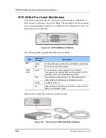
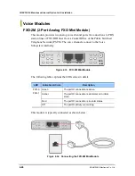
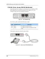
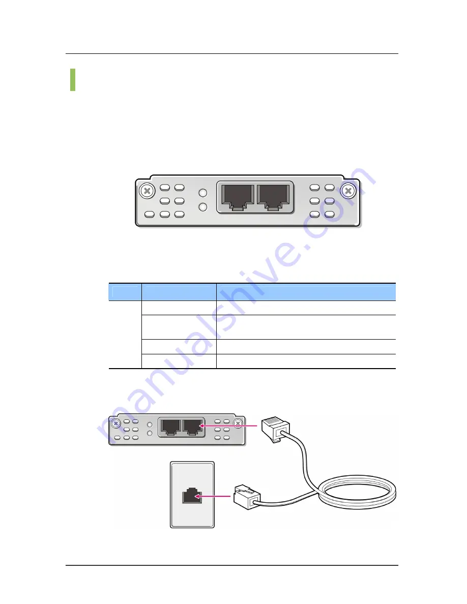
FXO-2M (2-Port Analog FXO Mini Module) 

This module provides two analog voice channel ports for connections to PBX 
station lines or FXS/DID lines from a Central Office of the Public Switched 
Telephone Network (PSTN). The voice channels connect to the Voice 
Subsystem internally. 
 

Figure 4.33    FXO-2M Mini Module 

 
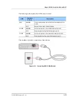
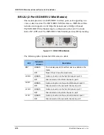
The following table explains the LEDs states in detail. 
 

LED 

Indication & Color 

Description 

Green 

The port0/1 connection is active. 

Amber 

The port0/1 connection is abnormal or in initial 
state. 

Red 

The port0/1 connection is in alarm status. 

FXO-0
FXO-1

Off 

The port0/1 activity is occurring. 

 
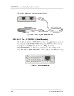
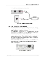
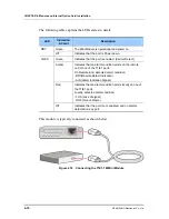
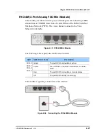
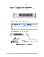
This module is typically connected as shown below: 
 

Figure 4.34    Connecting the FXO-2M Mini Module 

FXO-0

FXO 

-2M 

FXO-1

Summary of Contents for Ubigate iBG2006

Page 1: ......

Page 2: ...pany and product names may be trademarks of the respective companies with which they are associated This manual should be read before the installation and operation and the operator should correctly install and operate the product by using this manual This manual may be changed for the system improvement standardization and other technical reasons without prior notice If you have a question for th...

Page 3: ...ommunications Operation of this equipment in a residential area is likely to cause harmful interference in which case the user will be required to correct the interference at his own expense FCC Requirements This equipment the Ubigate iBG2006 complies with Part 68 of the FCC rules and the requirements adopted by the ATCA On the bottom of this equipment is a label that contains among other informat...

Page 4: ...structions for details FCC Part 68 This equipment complies with Part 68 of the FCC rules The FCC Part 68 label is located on the bottom chassis panel This label contains the FCC Registration Number and Ringer Equivalence Number REN for this equipment If requested this information must be provided to your telephone company Connection to the telephone network should be made by using standard modular...

Page 5: ... discontinuance of service may be required But if advance notice isn t practical the telephone company will notify the customer as soon as possible Also you will be advised of your right to file a complaint with the FCC if you believe it is necessary Changes to Telephone Company Equipment or Facilities The telephone company may make changes in its facilities equipment operations or procedures that...

Page 6: ... Equipment with Direct Inward Dialing DID ALLOWING THIS EQUIPMENT TO BE OPERATED IN SUCH A MANNER AS TO NOT PROVIDE FOR PROPER ANSWER SUPERVISION IS A VIOLATION OF PART 68 OF THE FCC S RULES PROPER ANSWER SUPERVISION IS WHEN A This equipment returns answer supervision to the Public Switched Telephone Network PSTN when DID calls are y Answered by the called station y Answered by the attendant y Rou...

Page 7: ...quipment connected to AC power sources This has been identified as a major nationwide problem Music on Hold Warning In accordance with US copyright laws a license may be required from the American Society of Composers Authors and Publishers ASCAP or other similar organizations if copyright music is transmitted through the Music on Hold feature SAMSUNG ELECTRONICS CO LTD hereby disclaims any liabil...

Page 8: ...system has been tested to comply with safety standards in the United States and Canada This system is listed with Underwriters Laboratories The cUL Mark is separately shown on the label The following statement from Underwriters Labs applies to the Ubigate iBG2006 System 1 Separation of TNV and SELV Pluggable A INSTRUCTION The separate protective earthing terminal provided on this product shall be ...

Page 9: ... shall be in compliance with the appropriate rules for terminating bonding jumpers in Part K of Article 250 of the National Electrical Code ANSI NFPA 70 and Article 10 of Part 1 of the Canadian Electrical Code Part 1 C22 1 Termination of the supplementary earthing conductor is permitted to be made to building steel to a metal electrical raceway system or to any earthed item that is permanently and...

Page 10: ... mechanical loading D Circuit Overloading Consideration should be given to the connection of the equipment to the supply circuit and the effect that overloading of the circuits might have on overcurrent protection and supply wiring Appropriate consideration of equipment nameplate ratings should be used when addressing this concern E Reliable Earthing Reliable earthing of rack mounted equipment sho...

Page 11: ...on chassis installation module installation interconnection and trouble shooting descriptions Document Content and Organization This manual is composed of five Chapters and two Annexes CHAPTER 1 Ubigate iBG2006 Overview y Ubigate iBG2006 Chassis y Ubigate iBG2006 Hardware CHAPTER 2 Pre Installation Requirements y Safety Recommendations y General Site Requirements y Inspecting the Ubigate iBG2006 y...

Page 12: ...ate iBG2006 CHAPTER 4 Module and Internal Option Card Installation y Safety Recommendations y Modules and Internal Option Cards Types y Port Numbering y Connecting Modules and Optional Cards y Installing Modules CHAPTER 5 Components Installation y Installing Compact Flash Memory Card y Installing DDRII SDRAM SODIMM ANNEX A Specifications ANNEX B Cable Specifications ...

Page 13: ...NING Provides information or instructions that the reader should follow in order to avoid personal injury or fatality CAUTION Provides information or instructions that the reader should follow in order to avoid a service failure or damage to the system NOTE Indicates additional information as a reference Information for Product and Technical Support For questions regarding the product and technica...

Page 14: ...INTRODUCTION XII SAMSUNG Electronics Co Ltd This page is intentionally left blank ...

Page 15: ...rect operation the following information must be given to the operator user and shall be read before the installation and operation Symbols Caution Indication of a general caution Restriction Indication for prohibiting an action for a product Instruction Indication for commanding a specifically required action ...

Page 16: ... instruments Invisible laser radiation may be emitted from disconnected fibers or connectors Do not stare into beams or view directly with optical instruments Laser radiation is present when the router is open Do not stare into beams or view directly with optical instruments To avoid electric shock do not connect safety extra low voltage SELV circuits as found in LAN ports to telephone network vol...

Page 17: ...mponents wear grounding wrist straps to avoid ESD damage to the card AC power to the Ubigate iBG2006 is double fused Fuses are installed on both line and neutral conductors A neutral fuse failure may present a hazard to service personnel Disconnect the AC Line Cord or remove both AC fuses before servicing the unit To avoid electric shock do not connect safety extra low voltage SELV circuits as fou...

Page 18: ... 10 pounds 4 5 kilograms on top of the chassis and do not stack routers on a tabletop Practice good safety habits Use two people to rack mount the Ubigate iBG2006 During the procedure wear grounding wrist straps to avoid ESD damage to the card To prevent damage to the Ubigate iBG2006 do not remove a Compact Flash memory card from the chassis while it is being accessed when the CF LED is blinking C...

Page 19: ...tories VI INTRODUCTION IX Purpose IX Document Content and Organization IX Conventions XI Information for Product and Technical Support XI Revision History XI SAFETY CONCERNS XIII Symbols XIII Warning XIV Caution XVI CHAPTER 1 Ubigate iBG2006 Overview 1 1 Ubigate iBG2006 Chassis 1 1 Ubigate iBG2006 Front Panel 1 2 Ubigate iBG2006 Rear Panel 1 4 Ubigate iBG2006 Hardware 1 6 Modules and Internal Opti...

Page 20: ...s 2 5 General Site Requirements 2 6 Site Preparation 2 6 Environment 2 6 Inspecting the Ubigate iBG2006 2 7 Required Tools and Materials 2 8 Cables 2 8 Tools 2 8 Materials 2 8 CHAPTER 3 Ubigate iBG2006 Installation 3 1 Mounting the Ubigate iBG2006 3 1 Tabletop Installation 3 1 Rack Mount Installation 3 2 To attach the mounting brackets 3 3 To secure the router to the rack 3 5 Grounding the Ubigate...

Page 21: ... Interface Modules 4 24 Voice Modules 4 26 Installing Modules 4 30 Installing Double Wide Mini Module 4 30 Installing Mini Modules 4 32 Installing Internal Option Card 4 33 Installing SFP Modules 4 34 CHAPTER 5 Components Installation 5 1 Installing Compact Flash Memory Cards 5 1 Installing DDR II SDRAM SODIMM 5 3 ANNEX A Specifications A 1 Ubigate iBG2006 Product Specifications A 1 Interface A 2 ...

Page 22: ...NTENTS XX SAMSUNG Electronics Co Ltd BRI 1ST BRI 2ST Mini Module Cable B 4 LMF 4M LMF 8M Module Cable B 5 T1E1 1M T1E1 2M Module Cable B 6 FXO 2M FXO 4M FXS 2M FXS 4MModuleCable B 7 ATOP 1 ATOI 1 Module Cable B 8 ...

Page 23: ...nsole Cable 3 8 Figure 3 9 Remotely Accessing an Ubigate iBG2006 3 9 Figure 3 10 AC Power Connection 3 11 Figure 4 1 Internal Option Card and Mini Modules 4 4 Figure 4 2 LAN Port Numbering 4 6 Figure 4 3 1 Port Mini Module Port Numbering 4 7 Figure 4 4 2 Port Mini Module Port Numbering 4 7 Figure 4 5 4 Port Mini Module Port Numbering 4 7 Figure 4 6 8 Port Mini Module Port Numbering 4 7 Figure 4 7 ...

Page 24: ... Module 4 26 Figure 4 34 Connecting the FXO 2M Mini Module 4 26 Figure 4 35 FXO 4M Mini Module 4 27 Figure 4 36 Connecting the FXO 4M Mini Module 4 27 Figure 4 37 FXS 2M Mini Module 4 28 Figure 4 38 Connecting the FXS 2M Mini Module 4 28 Figure 4 39 FXS 4M Mini Module 4 29 Figure 4 40 Connecting the FXS 4M Mini Module 4 29 Figure 4 45 Preparing a Wide Mini Module slot for Module insertion 4 30 Fig...

Page 25: ...Ubigate iBG2006 Installation Manual Ed 01 SAMSUNG Electronics Co Ltd XXIII Figure B 6 T1E1 2M T1E1 1M Module Cable B 6 Figure B 8 FXO 4M FXS 4M Module Cable B 7 Figure B 9 ATOP 1 ATOI 1 Module Cable B 8 ...

Page 26: ...TABLE OF CONTENTS XXIV SAMSUNG Electronics Co Ltd This page is intentionally left blank ...

Page 27: ...geable interface modules The router is a WAN LAN router that supports WAN LAN multi protocol routing An optional VPN IPSec Option Card provides high performance encryption and decryption services for the core router In addition an Ethernet switch modules and a Voice Subsystem may be incorporated into the router by adding appropriate optional cards and modules These enables iBG2006 to support Fast ...

Page 28: ...er is receiving power but malfunctioning SYS Off Router is not receiving power Solid green Power supply installed and operating normally Amber Power supply installed and powered off or fault condition detected PWR Off Power supply not present Solid green Fan is operating properly FAN Amber Fan present with failure Solid green VoP card present and enabled Amber or Red VoP card present with failure ...

Page 29: ...pact Flash not mounted or not being accessed Front Connector Description Connector Description Compact Flash Memory Slot Slot for Compact Flash Card USB Port Supports USB2 0 interface Console Port Serial port supporting local monitoring and configuring Auxiliary Port Serial port supporting remote monitoring Power Switch Power switch Power Connector AC power connector ...

Page 30: ...cription Figure 1 2 Ubigate iBG2006 Rear LED LED Indication Color Description Solid Green Link is established with speed 100 Mbps FE SFP LINK LED Off Link fail or not connected Blinking Amber Blinking Amber indicates transmit receive activity with speed 100 Mbps FE SFP ACT LED Off No activity Solid Green Link is established with speed 10 100 Mbps UTP FE Port Left LED Off Link fail or not connected...

Page 31: ... Supports Fast Ethernet interface Mini Module Slots A variety of data and interface cards can be plugged into Mini Module slots Depending on the widths of modules up to four modules can be plugged Card Guide Guides inserting Mini Module Remove guides when install double wide Mini Module LMF 8 M Ground Stud Screw holes for grounding lug Card Guide Mini Module Slots Mini Module Slots SFP Port LAN Po...

Page 32: ...mini module BRI 2ST 2 port ISDN BRI S T interface mini module BRI 1U 1 port ISDN BRI U interface mini module BRI 2U 2 port ISDN BRI U interface mini module T1E1 1M 1 port channelized T1 E1 mini module T1E1 2M 2 port channelized T1 E1 mini module WTE 1SM 1 port serial network mini module WTE 2SM 2 port serial network mini module ATOP 1 1 port ADSL over POTS mini module WAN Interface Modules ATOI 1 ...

Page 33: ...card The base configuration shipped from the factory is a 128MBytes Compact Flash memory card which can be upgraded to a maximum of 256MBytes The Ubigate iBG2006 supports one Compact Flash card slot Compact Flash is used to store application code images y Internal Flash Memory Ubigate iBG2006 includes 2MBytes of internal flash memory which is used to boot the router Power Supply Ubigate iBG2006 s ...

Page 34: ...r comes in and goes out When installing Ubigate iBG2006 ensure to make room around the system in order not to block air flow Figure 1 5 Ventilation Real Time Clock and NVRAM The Ubigate iBG2006 Real Time Clock and Non volatile RAM NVRAM provide two basic functions to the router y It provides a real time clock so that an Ubigate iBG2006 can maintain the correct date and time y It provides a small b...

Page 35: ...s Safety Recommendations The safety warnings that appear in this document such as the one below indicate a procedure that can harm you if not done correctly Electric hazard exists Verify the power is turned off Do not work on energized equipment Working on energized equipment can result in serious electrical shock Do not stare into beams or view directly with optical instruments To avoid electric ...

Page 36: ...r transceiver Small Form Pluggable SFP modules on some ports Laser radiation is present when the router is open Invisible laser radiation may be emitted from disconnected fibers or connectors Do not stare into beams or view directly with optical instruments Cover Panels Do not operate the Ubigate iBG2006 with missing blank faceplates and cover panels These covers prevent exposure to hazardous volt...

Page 37: ...erface cards Tighten the captive installation screws to ensure a proper connection when inserting modules or interface cards y When putting a module or interface card down always place it on an antistatic surface or in a static shielding container with the component board side facing up Best Practices Safety Practice these techniques to prevent accidents or injury at the installation site y Make s...

Page 38: ... air flow required for safe operation of the equipment is not compromised Mechanical Loading Mounting of the equipment in the rack should be such that a hazardous condition is not achieved due to uneven mechanical loading Circuit Overloading Consideration should be given to the connection of the equipment to the supply circuit and the effect that overloading of the circuits might have on overcurre...

Page 39: ...e failure may present a hazard to service personnel Disconnect the AC Line Cord or remove both AC fuses before servicing the unit PoE Requirements The Ubigate iBG2006 PoE ports are only intended for installation in Environment A as defined in IEEE 802 3af All interconnected equipment must be contained within the same building including the interconnected equipment s associated LAN connections Gene...

Page 40: ...ials required for installation Environment Site location is important for the proper operation of Ubigate iBG2006 Place the unit in a clean and dry environment with adequate air circulation Allow two to three feet additional clearance around the router for access to the cable connectors on the front and rear panels The selected installation site must meet basic environmental requirements The follo...

Page 41: ...f the shipping carton to ensure that you have received the following y Ubigate iBG2006 body y Console cable DB 9 to RJ 45 cable adapter y Rack mount package including Two 19 inch rack mount brackets Eight bracket screws y Surface adhesive rubber adhesive rubber Feet 4 pieces y Ground screw including lug and washer y Quick Start Guide y Manual CD Inspect the Ubigate iBG2006 for damage that may have...

Page 42: ...nnex B for pinout information y Console cable for console connection to terminal y Ethernet 10 100Base T CAT 5 UTP cable for a LAN connection Tools The following tools are required to install these routers y 2 Phillips screwdriver to attach the rack mounting brackets to the Ubigate iBG2006 y 3 Phillips screwdriver to attach the Ubigate iBG2006 to the equipment rack y Small flat blade screwdriver f...

Page 43: ...Tabletop Installation Place the Ubigate iBG2006 on a clean flat and stable surface with a minimum available footprint of 18 by 19 inches Allow sufficient room at the front rear and side of the unit for interface cabling power cord clearance and adequate ventilation Apply the rubber feet 4 included to the bottom of the chassis prior to placing the unit on a surface or when stacking several units on...

Page 44: ...t an air gap between the units and they can be intermingled with other Ubigate iBG2006 products or other vendor equipment However the cumulative required empty space for the number of Ubigate iBG2006s mounted in a rack must be accounted for in that rack This required empty space can be all above all below or a combination of above and below the installed router s Other vendor equipment installed i...

Page 45: ...e equipment rack should be located in an area with sufficient clearance for cabling and adequate ventilation Attach the mounting brackets to the Ubigate iBG2006 before securing the router to the rack To attach the mounting brackets 1 Select one of the three possible mounting positions on the sides of the router chassis And fasten the bracket using M4xL8 screw with the power of 5 4kgf y Bracket ins...

Page 46: ...tallation for center mounting y Bracket installation for front mounting Figure 3 4 Bracket installation for front mounting 2 Attach the other bracket to the corresponding position on the other side of the router When you install brackets as shown in the first and third figures it is recommended to attach the chassis support to the rack ...

Page 47: ... Lift the Ubigate iBG2006 assembly into the rack and align the bracket holes with the desired holes Practice good safety habits Use two people to rack mount the router 2 Attach the Ubigate iBG2006 to the rack according to the instructions provided by the rack manufacturer Figure 3 5 Rack mounting the Router ...

Page 48: ...PTER 3 Ubigate iBG2006 Installation 3 6 SAMSUNG Electronics Co Ltd Grounding the Ubigate iBG2006 Connect the Chassis as shown in the following figure to a reliable earth ground Figure 3 6 Ground Connection ...

Page 49: ...rk facility environment LAN Interface The Ubigate iBG2006 accommodates several network connections Use a Category 5 minimum Ethernet cable with RJ 45 connectors to connect to the network 1 Insert the RJ 45 connector on one end of the cable in any of the Ethernet ports Figure 3 7 Connecting LAN Cables 2 Connect the RJ 45 connector on the other end of the cable to the designated network Make sure th...

Page 50: ...to a PC running terminal emulation software your Ubigate iBG2006 is provided with an RJ 45 to DB 9 adapter cable To assemble and connect the console cable 1 Connect the RJ 45 8 conductor to the console port on the Ubigate iBG2006 Figure 3 8 Connecting Console Cable 2 Connect the adapter with the female DB 9 connector to the communications port on the workstation or terminal 3 Configure the worksta...

Page 51: ...and reboot the router Do not configure the modem to send result codes or echo commands Doing so may cause the router to hang Refer to your modem documentation for guidelines about establishing an asynchronous DCE to DCE connection between these two devices through the public switch telephone network PSTN Use an RJ 45 to DB 9 or DB 25 adapter cable to connect the router to a modem 1 Connect the RJ ...

Page 52: ...cessary If a workstation is used for the console use VT 100 terminal emulation software or equivalent and configure the software as specified for modems A modem connected to the Console port of an Ubigate iBG2006 and set for verbose mode configured to send result codes or echo commands can prevent the router from booting up properly Ubigate iBG2006 recommends that the user configures the modem to ...

Page 53: ...EE802 3af PoE functionality This chapter describes how to power up the Ubigate iBG2006 Connecting AC Power To connect power to the AC power supply connect the AC power connector to the power supply Connect the other end to a grounded power receptacle rated for the Ubigate iBG2006 Before connecting cables or performing maintenance on a Ubigate iBG2006 always wear an ESD preventative wrist strap Mak...

Page 54: ... Ensure that the Ubigate iBG2006 is connected to a power source 2 Press the rocker switch on the Ubigate iBG2006 back panel to the on position The fans start the LEDs cycle and the router performs a self test At the successful conclusion of the self test sequence the Power LED illuminates green Other status LEDs will be in various states This is a normal condition when the router is not configured...

Page 55: ... carton and packing material in case you need to return the equipment to Samsung Electronics Electric hazard exists Verify the power is turned off Do not work on energized equipment Working on energized equipment can result in serious electrical shock This equipment must be installed and maintained by properly trained service personnel Make sure the proper electrical service is available before pl...

Page 56: ...ow through the chassis They also prevent electromagnetic interference EMI that might disrupt other equipment To avoid electric shock do not connect safety extra low voltage SELV circuits as found in LAN ports to telephone network voltage TNV circuits as found in WAN ports Be sure to follow connection instructions carefully Electrostatic Discharge ESD Warning When handling Ubigate iBG2006 component...

Page 57: ...re a proper connection when inserting modules or interface cards y When putting a module or interface card down always place it on an antistatic surface or in a static shielding container with the component board side facing up General Maintenance Guidelines Keep all Ubigate iBG2006 modules and interface cards dry and dust free and stored in electrical equipment friendly environments ...

Page 58: ...owing limitations Voice service modules such as FXO FXS and T1 E1 cards if they are used to carry voice traffic can be plugged into all of the four slots However data service modules cannot be plugged into all of them Specifically LMF 4M can be plugged into slot 0 and slot 2 only LMF 8M can be plugged into slots 0 1 and slots 2 3 WAN modules such as T1E1 1M and T1E1 2M can be plugged into slot 1 a...

Page 59: ... to left starting with the next slot number based on the lower rows last left most numbered slot The main board is considered as network module slot 0 Mini modules are numbered from right to left starting with slot number zero If there is more than one row the bottom row is numbered first from right to left starting at slot zero then the next row up is numbered from right to left starting with the...

Page 60: ...ain board one Fast Ethernet SFP port and four Fast Ethernet UTP ports They are numbered 0 x since the main board is considered as network module slot 0 The SFP port is numbered as 0 0 Then the Fast Ethernet ports follow the numbering rule and are numbered right to left bottom to top starting with one Figure 4 2 LAN Port Numbering 0 4 0 3 0 2 0 1 0 0 ...

Page 61: ... or 3 Figure 4 3 1 Port Mini Module Port Numbering Figure 4 4 2 Port Mini Module Port Numbering Figure 4 5 4 Port Mini Module Port Numbering Figure 4 6 8 Port Mini Module Port Numbering BRI 2ST B1 B0 RDY ST 0 ST 1 B1 B0 0 X 1 0 X 0 2 0 3 1 FXO 3 FXO 2 FXO 1 FXO 0 FXO 4M 0 X 3 0 X 2 0 X 1 0 X 0 BRI 1ST B1 B0 RDY ST 0 0 X 0 FE 7 FE 6 FE 5 FE 4 FE 3 FE 2 FE 1 FE0 LMF 8M 0 X 3 0 X 2 0 X 1 0 X 0 0 X 7 ...

Page 62: ...4 Copper Fast Ethernet ports Main board LAN Ports 0 0 Optical Fast Ethernet port 0 0 0 Port zero on a mini module in sub slot zero Mini Module Ports 0 3 3 Port three on a mini module in sub slot three Double Wide Mini Module Port 0 0 0 thru 0 2 7 Port zero on a 8 port LAN mini module in sub slot zero through port seven on a 8 port LAN mini module in sub slot two ...

Page 63: ...must be installed onto the Main Board before it is inserted into the chassis Because it is mounted internally this card it is not hot swappable Figure 4 7 VPN A Internal Option Card VoP 16 VoP 32 VoP 64 VoIP Option Card The VoIP Option Card is for processing analog telephone voice features as well as handling survivable telephony features It includes a VoIP Processing DSP and a TDM Switch It is an...

Page 64: ...ST Mini Module The following table explains the LEDs states in detail LED Indication Color Description GREEN The module passed it s self test and is available to the router RDY OFF Reset Power down Removal state GREEN Active connection on the first B channel in port 0 ST 0 B0 OFF Disconnected on the first B channel in port 0 GREEN Active connection on the second B channel in port 0 ST 0 B1 OFF Dis...

Page 65: ...or Description GREEN The module passed it s self test and is available to the router RDY OFF Reset Power down Removal state GREEN Active connection on the first B channel in port 0 ST 0 B0 OFF Disconnected on the first B channel in port 0 GREEN Active connection on the second B channel in port 0 ST 0 B1 OFF Disconnected on the second B channel in port 0 GREEN Active connection on the first B chann...

Page 66: ...Mini Module This module provides one ISDN BRI U interface port supporting two voice or data timeslots The ISDN BRI U MM interfaces to ISDN Basic Rate networks and supports two 64 Kbps B channels and a 16Kbps d channel The ISDN BRI U Mini Module may be configured as either an LT network end or NT CPE end The ISDN BRI U Mini Module provides 2B1Q encoding Figure 4 13 BRI 1U Mini Module BRI 1U B1 B0 R...

Page 67: ... test and is available to the router RDY OFF Reset Power down Removal state GREEN Active connection on the first B channel in port 0 U 0 B0 OFF Disconnected on the first B channel in port 0 GREEN Active connection on the second B channel in port 0 U 0 B1 OFF Disconnected on the second B channel in port 0 This module is typically connected as shown below Figure 4 14 Connecting BRI 1U Mini Module ...

Page 68: ...i Module The following table explains the LEDs states in detail LED Indication Color Description GREEN The module passed it s self test and is available to the router RDY OFF Reset Power down Removal state GREEN Active connection on the first B channel in port 0 U 0 B0 OFF Disconnected on the first B channel in port 0 GREEN Active connection on the second B channel in port 0 U 0 B1 OFF Disconnecte...

Page 69: ...runk interface for voice data and integrated voice and data applications The Mini Module provides basic structured and unstructured service for T1 or E1 networks The Mini Module can be used to provide a trunk interface for voice and data services to provide fractional n x 64 kbps service for WANs Frame Relay or leased line or to provide time division multiplexing TDM drop and insert voice and data...

Page 70: ...Detect Amber Indicates that an alarm condition exists on the remote end of one of the T1 E1 ports On Remote End detected alarm condition RDI Remote Detect Indication AIS Alarm Indication Signal Red Indicates that an alarm condition exists locally on one of the T1 E1 ports Locally detected alarm condition LOS Loss of signal OOF Out of Frame LNK 0 Off Indicates that the port is not enabled and no al...

Page 71: ...TDM drop and insert voice and data integration services The T1 E1 Mini Module provides voice and data access to the PSTN domain through TDM ports and includes an integrated channel service unit data service unit CSU DSU Figure 4 19 T1E1 2M Mini Module The following table explains the LEDs states in detail LED Indication Color Description Green The Mini Module is operational and power on RDY Off In...

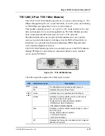
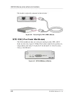
Page 72: ...ting the T1E1 2M Mini Module WTE 1SM 1 Port Serial Mini Module This Mini module provides one serial port running in either DTE or DCE mode at a data rate of up to 8 0 Mbps The interface mode for the port may be independently selected as V 35 RS 232 V 28 RS 449 V 11 EIA 530 EIA 530A or X 21 RS 422 Figure 4 21 WTE 2SM Network Module SERIAL0 LNK0 RDY WTE 2SM ...

Page 73: ...n Green indicates normal operation The module is connected to the external DSU and the signals TA DTE available and CA DCE available are active Red Red indicates serial interface error Mismatch between serial cable and interface type or operation mode Amber Loopback mode on LNK 0 Off LED off indicates that the port is neither connected to the DSU nor in loopback mode This module is typically conne...

Page 74: ... LED Indication Color Description Green All diagnostics pass and the Network Module is operational RDY Off Power down or removal status Green Green indicates normal operation The module is connected to the external DSU and the signals TA DTE available and CA DCE available are active Red Red indicates serial interface error Mismatch between serial cable and interface type or operation mode Amber Lo...

Page 75: ... that the Link is established Blinking Green Indicates that the Link is being established LINK Off Indicates that the port is not enabled Solid Green Indicates that the transmit receive is not active Blinking Green Indicates that the transmit receive is active ACT Off Indicates that the port is not enabled LAN Port LEDs LED Indication Color Description Solid Green Link is established with speed 10...

Page 76: ...riber and the central office Figure 4 27 ATOI 1 Mini Module The following table explains the LEDs states in detail ADSL Port LEDs LED Indication Color Description Solid Green Indicates that the Link is established Blinking Green Indicates that the Link is being established LINK Off Indicates that the port is not enabled Solid Green Indicates that the transmit receive is not active Blinking Green I...

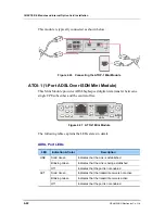
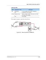
Page 77: ...ription Solid Green Link is established with speed 10 100 Mbps Link Off Link failure or no connection Blinking Orange Blinking orange indicates transmit receive activity with speed 10 100 Mbps Activity Off No activities This module is typically connected as shown below Figure 4 28 Connecting the ATOI 1 Mini Module ...

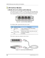
Page 78: ...t2 only in order to provide 10 100 Ethernet connectivity Figure 4 29 4 port Fast Ethernet Mini Module The following table explains the LEDs states in detail LED Indication Color Description Solid Green Link is established with speed 10 100 Mbps Link Off Link Fail or no connect Blinking Orange Blinking Orange indicates transmit receive activity with speed 10 100 Mbps Activity Off No activities This...

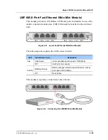
Page 79: ... 4 31 8 port Fast Ethernet Wide Mini Module The following table explains the LEDs states in detail LED Indication Color Description Solid Green Link is established with speed 10 100 Mbps Link Off Link Fail or no connect Blinking Orange Blinking Orange indicates transmit receive activity with speed 10 100 Mbps Activity Off No activities This module is typically connected as shown below Figure 4 32 ...

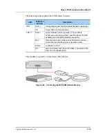
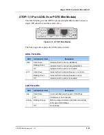
Page 80: ...work PSTN The voice channels connect to the Voice Subsystem internally Figure 4 33 FXO 2M Mini Module The following table explains the LEDs states in detail LED Indication Color Description Green The port0 1 connection is active Amber The port0 1 connection is abnormal or in initial state Red The port0 1 connection is in alarm status FXO 0 FXO 1 Off The port0 1 activity is occurring This module is...

Page 81: ... to the Voice Subsystem internally Figure 4 35 FXO 4M Mini Module The following table explains the LEDs states in detail LED Indication Color Description Green The port0 1 2 3 connection is active Amber The port0 1 2 3 connection is abnormal or in initial state Red The port0 1 2 3 connection is in alarm status FXO 0 FXO 1 FXO 2 FXO 3 Off The port0 1 2 3 activity is occurring This module is typical...

Page 82: ...elephones or fax machines The voice channels connect to the Voice Subsystem internally Figure 4 37 FXS 2M Mini Module The following table explains the LEDs states in detail LED Indication Color Description Green The port0 1 connection is active FXS 0 FXS 1 Amber The port0 1 connection is abnormal or in initial state This module is typically connected as shown below Figure 4 38 Connecting the FXS 2...

Page 83: ... The voice channels connect to the Voice Subsystem internally Figure 4 39 FXS 4M Mini Module The following table explains the LEDs states in detail LED Indication Color Description Green The port0 1 2 3 connection is active FXS 0 FXS 1 FXS 2 FXS 3 Amber The port0 1 2 3 connection is abnormal or in initial state This module is typically connected as shown below Figure 4 40 Connecting the FXS 4M Min...

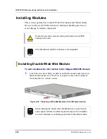
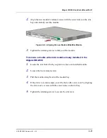
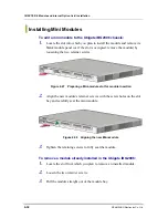
Page 84: ...odule and Mini modules are hot swappable Installing Double Wide Mini Module To add a double wide mini module to the Ubigate iBG2006 chassis 1 Locate the slot into which you plan to install the module and remove its blank module panel or if the slot is occupied remove the module by loosening the two retainer screws Figure 4 45 Preparing a Wide Mini Module slot for Module insertion Before installing...

Page 85: ...ing screws to fully seat the module To remove a double wide mini module already installed in the Ubigate iBG2006 1 Locate the slot from which you plan to remove an installed module 2 Loosen the two retainer screws 3 Pull the module straight out of the module bay 4 If the slot is to remain empty cover the hole with a slot cover by aligning the slot cover s screws with the screw holes on the slot ba...

Page 86: ...ening the two retainer screws Figure 4 47 Preparing a Mini module slot for module insertion 2 Align the new module s retainer screws with the screw holes on the slot bay and carefully seat the mini module Figure 4 48 Aligning the new Mini module 3 Tighten the retaining screws to fully seat the module To remove a module already installed in the Ubigate iBG2006 1 Locate the slot from which you plan ...

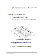
Page 87: ...secure the slot cover Installing Internal Option Card To add an internal option card 1 Pull the main module straight out of the slot bay 2 Insert an internal option card into the card connector of the main board 3 Tighten the screws to fully seat the internal option card Figure 4 49 Installing the Internal Option Card To remove an internal option card already installed 1 Loosen the screws 2 Discon...

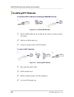
Page 88: ...e 4 50 Installing SFP Modules 1 Insert an SFP module into the module bay into which you plan to install the module 2 Remove the SFP module cap 3 Connect an optical cable to the SFP module To remove SFP modules Figure 4 51 Removing SFP Modules 1 Disconnect the optical cable 2 Pull the handle down 3 Pull the module straight out of the module bay 4 Cover the SFP module cap ...

Page 89: ...ompact Flash Memory Cards Compact Flash memory cards are sensitive to Electrostatic Discharge ESD Damage which can occur when electronic cards or components are handled improperly resulting in complete or intermittent failures To prevent damage to the Ubigate iBG2006 do not remove a Compact Flash memory card from the chassis while it is being accessed when the CF LED is blinking ...

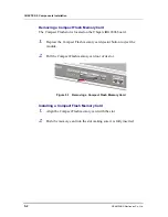
Page 90: ... iBG2006 board 1 Depress the Compact Flash memory card ejector button to eject the module 2 Pull the Compact Flash memory card out of its slot Figure 5 1 Removing a Compact Flash Memory Card Installing a Compact Flash Memory Card 1 Align the Compact Flash memory card with the slot 2 Push the memory card into the slot making sure it is fully inserted ...

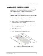
Page 91: ...SO DIMM The memory module for the Ubigate iBG2006 is located on the system board 1 Pull the main module straight out of the slot bay The SODIMM slot location is shown under internal option cards if any 2 Orient the DDR II SDRAM SODIMM polarization notch with the SODIMM connector on the system board 3 Press the SODIMM into the slot making sure it is fully seated the slot latches will engage the SOD...

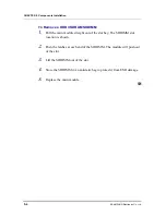
Page 92: ... 1 Pull the main module straight out of the slot bay The SODIMM slot location is shown 2 Push the latches at each end of the SODIMM The module will push out of the slot 3 Lift the SODIMM out of the slot 4 Store the SODIMM in an antistatic bag to protect it from ESD damage 5 Replace the main module ...

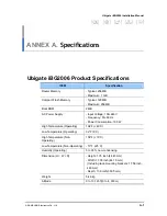
Page 93: ...Supply Input Voltage 100 240 V Frequency 50 60 Hz Power Consumption 100 W High Temperature Operating 104 F 40 C Low Temperature Operating 32 F 0 C High Temperature Non Operating 158 F 70 C Low Temperature Non Operating 13 F 25 C Humidity Operating 5 to 95 non condensing Dimension H W D Height 1 75 inch 44 45 mm Width 17 38 inch 441 5 mm Including rack mounting brackets 17 56 inch 446 mm Depth 13 8...

Page 94: ... FCC Part 68 Interface The following tables provide specifications for T1 WAN Serial WAN and Ethernet LAN interfaces E1 WAN Interface Specifications Descriptions Receive line rate 2 048 Mbps 50 ppm payload 1 984 Mbps Line code HDB3 Framing CRC non CRC ITU G 704 and unframed Input signal DSX 1 0 to 24 dB Output signal build out long haul or short haul Impedance 75 or 120 ohm Connectors RJ 48C Timin...

Page 95: ... AT T TR 54016 1986 AT T TR 54016 1989 ANSI T1 403 1989 Input signal DSX 1 0 to 24 dB Output signal build out 0 7 5 dB 5 dB Equalization 0 to 655 ft DSX 1 Impedance 100 ohm Connectors RJ 48C Timing Internal or network Pulse density AT T TR 62411 HDLC Inversion forced Ethernet LAN Interface Specifications Descriptions Data flow Full duplex or half duplex Connectors RJ 45 Data speed 10 100 Mbps auto...

Page 96: ...ANNEX A Specifications A 4 SAMSUNG Electronics Co Ltd This page is intentionally left blank ...

Page 97: ...able Cable Shape Figure B 1 Console Port Cable Cable Signaling and Pinout Console Port DTE RJ 45 to RJ 45 Rollover Cable RJ 45 to DB 9 Terminal Adapter connected to Rollover Cable Console Device Signal RJ 45 Pin DB 0 Pin Signal RTS 1 8 CTS DTR 2 6 DSR TxD 3 2 RxD GND 4 5 GND GND 5 5 GND RxD 6 3 TxD DSR 7 4 DTR CTS 8 7 RTS ...

Page 98: ... Cable Cable Shape Figure B 2 Auxiliary Port Cable Cable Signaling and Pinout Auxiliary Port DTE RJ 45 to DB 25 Modem Adapter Modem Signal RJ 45 Pin DB 9 Pin DB 25 Pin Signal RTS 1 7 4 RTS DTR 2 4 20 DTR TxD 3 3 2 TxD GND 4 5 7 GND GND 5 5 7 GND RxD 6 2 3 RxD DSR 7 6 8 DCD CTS 8 8 5 CTS ...

Page 99: ...SAMSUNG Electronics Co Ltd B 3 BRI 1U BRI 2U Mini Module Cable Cable Shape Figure B 3 BRI 2U Mini Module Cable Cable Signaling and Pinout 8 Pin1 Function 3 No connection 4 Signal Tip 5 Signal Ring 6 No connection 1 Pins 1 2 7 and 8 are not used ...

Page 100: ... Signaling and Pinout 8 Pin1 TE2 NT3 Polarity 3 No connection 4 Signal Tip 5 Signal Ring 6 No connection 1 Pins 1 2 7 and 8 are not used 2 TE refers to terminal terminating layer 1 aspects of TE1 TA and NT functional groups this applies to the ISDN BRI S T WIC 3 NT refers to network terminating layer 1 aspects of NT1 and NT2 functional groups ...

Page 101: ...feet y Standard Straight Through Wiring both ends are the same y 10 100Base T interfaces Figure B 5 LMF 4M LMF 8M Module Cable Cable Signaling and Pinout RJ45 Pin Wire Color T568A 1000Base T Signal 1 White Green BI_DA 2 Green BI_DA 3 White Orange BI_DB 4 Blue BI_DC 5 White Blue BI_DC 6 Orange BI_DB 7 White Brown BI_DD 8 Brown BI_DD ...

Page 102: ...B 6 SAMSUNG Electronics Co Ltd T1E1 1M T1E1 2M Module Cable Cable Shape y RJ 48C to RJ 48C Cable Figure B 6 T1E1 2M T1E1 1M Module Cable Cable Signaling and Pinout 1 RXPING 4 TXRING 2 RXTIP 5 TXTIP 4 TXRING 1 RXRING 5 TXTIP 2 RXTIP ...

Page 103: ...SAMSUNG Electronics Co Ltd B 7 FXO 2M FXO 4M FXS 2M FXS 4M Module Cable Cable Shape Figure B 8 FXO 4M FXS 4M Module Cable Cable Signaling and Pinout RJ 11 connector RJ 11 connector Pin Signal Signal Pin 1 1 2 2 3 Ring Ring 3 4 Tip Tip 4 5 5 6 6 ...

Page 104: ...B 8 SAMSUNG Electronics Co Ltd ATOP 1 ATOI 1 Module Cable Cable Shape Figure B 9 ATOP 1 ATOI 1 Module Cable Cable Signaling and Pinout RJ 11 connector RJ 11 connector Pin Signal Signal Pin 1 1 2 2 3 Ring Ring 3 4 Tip Tip 4 5 5 6 6 ...

Page 105: ...s reserved Information in this manual is proprietary to SAMSUNG Electronics Co Ltd No information contained here may be copied translated transcribed or duplicated by any form without the prior written consent of SAMSUNG Information in this manual is subject to change without notice ...

Page 106: ...EQNA 000051 Ed 01 ...

Reviews: