


Operations & Installation
2-28
2-7 Ring
You can use the
Ring
menu to customize various sound settings such as ring volume, type and tone. Also you
can delay the ring for a specified time via the menu.
2-7-1 Choosing Ring Tone
You can define your own ring sound. Ten ring tones are available.The factory default setting is ÔTone 1Õ.
1. In the Standby mode, press the
Menu
soft key.
2. Press the
soft key repeatedly until
Ring
appears, then press the
Select
soft key.
Ring Tone
appears.
3. Press the
Select
soft key to access the option.
4. Press the
soft key repeatedly until you choose a desired ring tone. Each time you press the
soft key,
the handset sounds the ring you have chosen.
5. Press the
OK
soft key to confirm the setting.
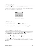
2-7-2 Adjusting Ring Volume
1. In the Standby mode, press the
Menu
soft key.
2. Press the
soft key repeatedly until
Ring
appears, then press the Select soft key.
3. Press the
soft key repeatedly until
Ring Volume
appears, then press the
Select
soft key. The current
Ring Volume setting appears.
4. Press the
or
key on the side of the phone to choose the volume level you want.
Each time you press
or
key, the handset sounds the ring with the level you have chosen.
The ring volume is displayed as bars in the LCD window. The more bars you see, the louder the volume is.
5. Press the
OK
soft key to confirm the setting.
Summary of Contents for SP-R6100
Page 3: ......
Page 52: ...Exploded View Parts List 3 6 3 6 SP R6100 CHARGER Exploded View 6 8 7 1 2 3 4 5 9 ...
Page 54: ...Exploded View Parts List 3 8 SP R6100 PACKING Exploded View 3 8 3 7 4 1 5 8 2 6 9 ...
Page 67: ...6 1 6 PCB Diagrams 6 1 SP R6100 Base PCB I ...
Page 68: ...PCD Diagrams ...
Page 69: ...6 2 SP R6100 Base PCB II 6 2 ...
Page 70: ...PCD Diagrams ...
Page 71: ...6 3 SP R6100 Handy PCB I 6 3 ...
Page 72: ...PCD Diagrams ...
Page 73: ...6 4 SP R6100 Handy PCB II 6 4 ...
Page 74: ...PCD Diagrams ...
Page 75: ...6 5 SP R6100 Key PCB I PCD Diagrams 6 5 ...
Page 76: ...6 6 SP R6100 Key PCB II PCB Diagrams 6 6 ...
Page 77: ...6 7 SP R6100 Charger PCB I 6 7 PCD Diagrams ...
Page 78: ...6 8 SP R6100 Charger PCB II PCB Diagrams 6 8 ...
Page 79: ...Schematic Diagrams 7 1 7 Schematic Diagrams 7 1 SP R6100 Hand LOGIC ...
Page 81: ...Schematic Diagrams 7 3 7 3 SP R6100 BASE LOGIC ...
Page 82: ...Schematic Diagrams 7 4 7 4 SP R6100 Base CLIP ...
Page 84: ...Schematic Diagrams 7 6 HAND KEY 7 6 ...


