background image

3-24

I

3-23

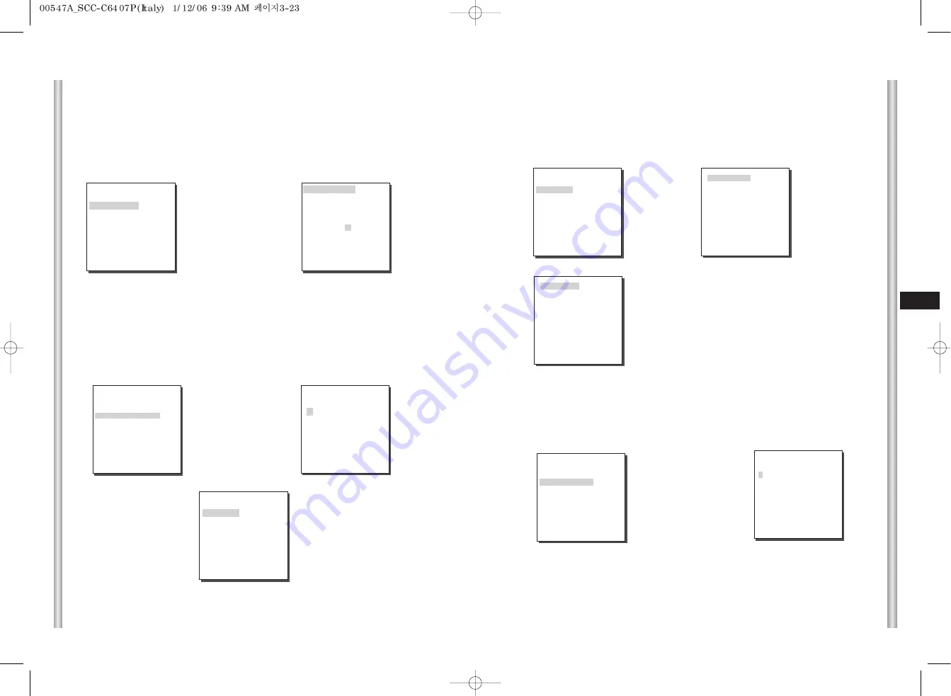
POSIZIONE

Il menu POSIZIONE designa la posizione limite Destra/Sinistra della
zona. Inserire la schermata d'impostazione per muovere il PAN, quindi
selezionare una posizione limite Sinistra e premere [ENTER]. Muovere
nuovamente PAN per selezionare una posizione limite destra e premere
[ENTER]. Adesso la configurazione zona è completata. 

premere

[Enter]

Dopo operazione PAN

finisce con premedno la

chiave [Enter]

PROG INIZIO!

IMPOSTA ZONA    0

POSIZIONE                  ...
ID ZONA ATTIVO

...

ZONA ABILITATA    

ON

USCITA

ESCI

Ë Dopo

operazione

P/R/Z preme la

chiave [Enter]. 

PROG FINE!

IMPOSTA ZONA    0

POSIZIONE                  ...
ID ZONA ATTIVO

...

ZONA ABILITATA    

ON

USCITA

ESCI

ID ZONA ATTIVO 

Questa funzione è usata per assegnare fino a 12 ID per ciascuna zona,
usando i tasti Sinistra, Destra, Su o Giù. Si può selezionare la posizione ID
dal menu secondario di posizione.

ZONA ABILITATA

Questa funzione attiva o disattiva l'indicazione ID ZONA. 

premere

[Enter]

ZONE AREA ID 0

A  B C D E F G H I  J  K  L
M N O P Q R S T U V W X
Y  Z  0 1 2 3 4 5 6 7 8  9

:  !  -  +  

( ) /

SP 

ï î

SP

POSIZION...
RET
ZONE 0........

(ZONA PROG)

ZONE PRIVACY           ...
IMPOSTA DIR. ZONA  ON...
IMPOSTA ZONA          OFF

USCITA                       ESCI

IMPOSTA NORD

N

premere

[Enter]

IMPOSTA DIR. ZONA

Nella modalità “IMPOSTA DIR. ZONA ON…”, premere il tasto [ENTER]
per accedere alla schermata IMPOSTA NORD. Muovere PAN per
impostare la posizione NORD e premere [ENTER]. Spostare il PAN per
impostare la posizione NORD, sarà visualizzata la N(Nord), NE
(Nord-Est), E(East), SE(Sud-Est), S(Sud), SW(Sud-Ovest), O(Ovest),
NO(Nord-Ovest).

IMPOSTA ZONA    0

POSIZIONE                  ...
ID ZONA ATTIVO

...

ZONA ABILITATA    

ON

USCITA

ESCI

premere

[Enter]

IMPOSTA ZONA 

Dalla schermata IMPOSTA ZONA ON… premere il tasto [ENTER] per
accedere alla scher mata MAPPA ZONA . In questa schermata
selezionare un numero di zona e premere [ENTER] per accedere alla
schermata d'impostazione ZONA.

premere

[Enter]

(MAPPA ZONE PRIVACY)

0 *

1          2          3    

4          5          6          7 

RET 

ZONA PROG)

ZONE PRIVACY           ...
IMPOSTA DIR. ZONA  OFF
IMPOSTA ZONA          ON...

USCITA                       ESCI

Summary of Contents for SCC-C6407

Page 1: ...Part AB68 00547A 00 Printed in China SCC C6407 P E D F Es I SmartDome Camera Owner s Instructions Benutzerhandbuch Manuel d instruction Manual del usuario Istruzioni per l uso ...

Page 2: ...a on a wall or ceiling fasten it securely and firmly A falling camera may cause personal injury 1 Read these instructions 2 Keep these instructions 3 Heed all warnings 4 Follow all instructions 5 Do not use this apparatus near water 6 Clean only with dry cloth 7 Do not block any ventilation openings Install in accordance with the manufacturer s instructions 8 Do not install near any heat sources s...

Page 3: ...ture over 122 F low temperature below 14 F or high humidity Doing so may cause fire or electrical shock 3 Avoid a location which is exposed to direct sunlight or near heat sources such as heaters or radiators Neglecting to do so may result in a risk of fire 4 If you want to relocate the already installed product be sure to turn off the power and then move or reinstall it 5 Install in a well ventil...

Page 4: ... in detailed in Chapter 3 Setup Menu Overview The instructional manual is best used when read from beginning to end but for users wanting to read only the part they need here are the Chapter summaries Chapter 1 SCC C6407 P Overview includes a brief introduction of the SCC C6407 P part names and functions and Switch Settings Chapter 2 SCC C6407 P Installation explains the installation procedures of...

Page 5: ...31 8 SYSTEM INFO 3 32 9 SHORT KEYS 3 33 Product specifications 3 35 Before Usage 1 1 Chapter 1 SCC C6407 P Overview 1 5 SCC C6407 P Introduction 1 6 Locations of Control 1 7 FRONT 1 7 BACK 1 8 ADAPTER CONNECTION 1 9 INITIAL SETTING 1 10 Setting RS 422A RS 485 termination 1 11 Chapter 2 SCC C6407 P Installation 2 1 Before Installing 2 2 Preparing the Cables 2 3 Cable Connection 2 4 Installing SCC C...

Page 6: ...to the black and white mode at night or in the environment with low illumination White Balance to control the brightness to the illumination Backlight Compensation under spotlight or utmost bright illumination Auto Focus to automatically adjust the focus to the subject movement Privacy zone to hide a specific area for personal privacy and PAN TILT for precise control at high speed The SCC C6407 P ...

Page 7: ...1 8 E 1 7 BACK Locations of Control FRONT ...

Page 8: ...02 SW703 1 2 3 4 5 6 7 8 ON OFF BAUD RATE 4800 BPS 9600 BPS 19200 BPS 38400 BPS PIN 5 ON OFF ON OFF PIN 6 ON ON OFF OFF A SAMSUNG HALF B SAMSUNG FULL PIN1 PIN2 PIN3 PIN4 A OFF OFF OFF OFF B ON OFF OFF OFF C OFF ON OFF OFF D ON ON OFF OFF E OFF OFF ON OFF F ON OFF ON OFF G OFF ON ON OFF H ON ON ON OFF I OFF OFF OFF ON J ON OFF OFF ON K OFF ON OFF ON L ON ON OFF ON M OFF OFF ON ON N ON OFF ON ON O O...

Page 9: ...s to the lowest RS 485 Half Duplex Organization n 32 Termination SW1 ON Division Termination using numbers 1 and 2 PIN turn to ON and it will be terminated RS 422A RS 485 Full Duplex Organization Division Division SW1 ON SW2 ON n 32 In this chapter we will check the contents of the package before installing the SCC C6407 P and prepare a power adapter suitable for the power supply system Power Cons...

Page 10: ...ed voltage before using the cable Video Cable The SCC C6407 P s cable is a BNC Cable for connecting the video output terminal to the video input terminal of the monitor Preparing the Cables 2 3 E 2 2 SCC C6407 P Bracket anchor Camera Holder Adapter Board Cover Body Owner s Instructions Screws Before Installing Checking Package Contents Please check that all components listed below are included in ...

Page 11: ...OUNT BRACKET SBR 100DCM This bracket is used for installing the SmartDome CAMERA in the plenum above the drop ceiling 2 WALL MOUNT ADAPTOR SADT 100WM This adaptor is used for installing the indoor housing or the outdoor housing for the SmartDome Camera on a wall 2 5 E 2 4 4 Adjust the switch below the Power Adapter to the proper voltage Then connect the Power Adapter s plug to the Power Connector ...

Page 12: ...lling the WALL MOUNT ADAPTOR SADT 100WM to a pole that is over 8 cm 2 76 in in diameter 3 INDOOR HOUSING SHG 120 This housing is used for installing the SmartDome Camera to an indoor wall or a ceiling 4 OUTDOOR HOUSING SHG 220 This housing is used for installing the SmartDome Camera to an outdoor wall or a ceiling 2 7 E 2 6 To install and use OUTDOOR HOUSING remove the Clear Case from the Camera b...

Page 13: ...PH M4 x 8 to assemble them Figure 5 6 Pull the safety wire from the case body and assembly it to the camera holder Figure 6 3 Figure 2 Assemble the BRKT ANCHOR on the ceiling and screw the 4 bolts in Figure 2 2 Make a hole in the ceiling where the camera will be installed The hole should be about ø185 4 Figure 3 4 Connect the various cables to the CAMERA ADAPTER See page 2 4 Figure 4 Figure 3 Figu...

Page 14: ...2 X10 EXIT QUIT SAVE PRESET VIDEO SET IRIS ALC WDR MANU SHUTTER OFF 1 100 1 120 1 1OK AUTOX2 X160 AGC OFF LOW HIGH MOTION S SLOW SLOW NORM FAST F FAST WHITE BAL ATW1 ATW2 AWC MANU DIS ON OFF FOCUS MODE AF MF ONEAF SPECIAL REVERSE OFF H V H V Y LEVEL 0 l C LEVEL 0 l DETAIL 0 l RET EXIT QUIT SAVE PRESET PRESET POSITION SET PRESET ID ON OFF VIDEO SET ON OFF PRESET SPEED 1 8 DWELL TIME 1 60S IMAGE HOL...

Page 15: ... PASSWORD DEFINED If the power is turned off after PRESET AUTO PAN SCAN PATTERN function is activated and no other control is made camera will do the same function after the power is turned on Menu setting is available only when tilt position is under 90 When tilt position is over 90 and menu on command is received pan will automatically rotate 180 and tilt will be move to the corresponding positi...

Page 16: ... is output together with black and white composite video signal BURST OFF The color burst signal is not output LEVEL You can set the brightness level that changes from COLOR mode to BW mode in 3 steps LOW MEDIUM and HIGH DURATION Set the HOLDING time for switching between COLOR and BW mode depending the changes in the amount of light You can set the HOLDING time to 10sec S 30sec 60sec or 300sec L ...

Page 17: ...USER and press ENTER you may vary the size and position of the area where you want to apply the MOTION detection function by yourself Press Left Right Up or Down to select an area size Press ENTER and then Left Right Up or Down to select a position Press ENTER again to move back to the upper menu Use ENTER and Left Right Up or Down to move and scale the MOTION detection area Press ENTER again and ...

Page 18: ...y adjust IRIS to the incoming light level Owing to this function you may set up the brightness level yourself The ALC Auto Light Control menu allows you for video output level setup The WDR Wide Dynamic Range menu allows you to set up the WDR level and the FLICKERLESS function For items in the BLC menu the user can set the size and location of the BLC area by pressing ENTER key after put the curso...

Page 19: ... the screen profit mostly effective when you photograph both indoor and outdoor In short this function provides you with the distinct reproduction of not only the indoor but also the outdoor Press ENTER to set up the WDR level and the FLICKERLESS function Press Enter WDR LEVEL1 L I H LEVEL2 L I H FLICKERLESS OFF RET VIDEO SET IRIS WDR SHUTTER OFF AGC OFF WHITE BAL ATW1 DIS ON FOCUS MODE AF SPECIAL...

Page 20: ... maximum AGC GAIN When the COLOR BW menu of the camera set is set to AUTO the AGC menu item is left dotted and the maximum AGC GAIN is fixed to HIGH MOTION The MOTION function is available only when the SHUTTER men is set to Slow Shutter AUTO being composed of 5 steps S SLOW SLOW NORM FAST F FAST S SLOW reduces the amount of AGC as much as possible to monitor subjects with no immobility in the dar...

Page 21: ...amera screen shaking incurred from vibration It is recommended to deactivate the DIS function in the no vibration environment Press Enter AWB MANUAL PRESET 3200K RET VIDEO SET IRIS ALC SHUTTER OFF AGC ON WHITE BAL MANU DIS ON FOCUS MODE AF SPECIAL EXIT QUIT You can select one of four modes for white balance adjustment as follows ATW1 ATW2 Auto Tracing White Balance Mode In these modes the color te...

Page 22: ... will be paused until PRESET finishes moving EXIT QUIT Does not save the selected information and returns to a higher menu SAVE Do saves the selected information and returns to a higher menu DEL Deletes the selected information and restores the DEFAULT Then returns to a higher menu 3 PRESET This is the menu that user sets the PAN TILT location Zoom Focus and screen condition so the camera can moni...

Page 23: ...rded as the ZONE area STYLE In the STYLE menu you may the shape of the PRIVACY ZONE area on the screen MOSAIC1 The privacy zone is displayed with the mosaic of 16 X 16 pixel MOSAIC2 The privacy zone is displayed with the mosaic of 32 X 32 pixel 4 ZONE SET The ZONE SET menu includes the setup of PRIVACY ZONE ZONE DIRECTION and ZONE AREA PRIVACY ZONE Move PAN TILT ZOOM to select an area that can inf...

Page 24: ...tion will be in action only at the higher magnification than the Zoom magnification as set Press Enter SET ZOOM PRIVACY ZONE SET 0 SET ZONE AREA ON SET ZOOM REVERSE OFF EXIT QUIT After P T Z control press ENTER After P T Z control press ENTER PRIVACY ZONE P T 3 PRIVACY ZONE P T 2 PRIVACY ZONE P T 4 SET ZONE AREA Press ENTER at the SET ZONE AREA position to enter the PRIVACY ZONE setup screen Contr...

Page 25: ...he ZONE AREA ID indication Press Enter ZONE AREA ID 0 A B C D E F G H I J K L M N O P Q R S T U V W X Y Z 0 1 2 3 4 5 6 7 8 9 SP ï î SP LOCATION RET ZONE 0 ZONE DIR SET Press the Enter key in the ZONE DIR SET ON mode to enter the NORTH SET screen MAP Move PAN to set the NORTH position and press ENTER Based on the North position the direction of N North NE North East E East SE South East S South SW...

Page 26: ...00 is used when uploading downloading the menu setup reset the PATTERN because it may be different with the first setting AUTO PAN After selecting the locations of two points PAN TILT of START and END it loops continuously in the set up SPEED The number of AUTO PAN is up to 4 5 AUTO SET The AUTO SET menu includes AUTO PAN PATTERN and SCAN and it is able to set up the AUTO PLAY motion Press Enter M...

Page 27: ... SET AUTO SET ALARM SET OTHER SET SYSTEM INFO AUTO SET AUTO PAN 1 PATTERN 1 SCAN 1 AUTO PLAY RET Press Enter AUTO SET AUTO PAN 1 PATTERN 1 SCAN 1 AUTO PLAY RET PATTERN SET 1 SET START POSITION AND ENTER PATTERN can be set upto 3 Choose 1 2 or 3 with the left or right key in the PATTERN SET and press ENTER to get into the PATTERN set up screen From the moment PATTERN 1 SET is gone for 2 minutes it ...

Page 28: ...f it is set to OFF the ALARM OUT motion will operate only when the ALARM is working Active Low and if it s set to ON the ALARM OUT will always operate regardless of the ALARM 6 ALARM SET It consists of 8 ALARM INPUTs and 3 ALARM OUTs It can sense an ALARM input from exterior SENSORs and it performs with PRESET or PATTERN function and outputs the ALARM OUT signals The Alarm will be recognized only ...

Page 29: ...nual operation of PAN TILT The speed may go up to 180 sec PAN AUTO CAL This function turns on or off Auto Calibration SCC C6407 P has the Auto Calibration function to improve the precision of LENS and PAN TILT motor You may set to OFF 6H 12H 18H 24H Without user s key input for the time designated by the user A C will appear on the screen while initializing LENS and PAN TILT D FLIP When D FLIP is ...

Page 30: ...AUTO RETURN will be available only when the function equivalent to AUTO PLAY a sub menu of AUTO SET has been built in Function Key CAMERA SET COLOR BW COLOR COLOR BW BW COLOR BW AUTO PRESET 1 2 8 Enter PRESET 1 2 9 Enter PRESET 1 3 0 Enter VIDEO SET IRIS WDR IRIS ALC FOCUS MODE AF FOCUS MODE MF FOUCS MODE ONEAF PRESET 1 3 1 Enter PRESET 1 3 2 Enter PRESET 1 3 3 Enter PRESET 1 3 4 Enter PRESET 1 3 ...

Page 31: ...IZE Weight Lives of Main Parts One Year for use of Full AF Rotated 10 000 000 Times 4 5 Years Product specifications SCC C6407 Contents Zoom lens single body WDR SmartDome CAMERA AC 24 10 60Hz 0 3Hz 22W NTSC STANDARD COLOR SYSTEM 1 4 inch WDR compatible Exview HAD CCD 768 H x 494 V 525 Lines 2 1 Interlace Horizontal 15 734 Hz INT 15 750 Hz L L Vertical 59 94 Hz INT 60 Hz L L INT LINE LOCK 480 TV L...

Page 32: ...hat it should not be disposed with other household wastes at the end of its working life To prevent possible harm to the environment or human health from uncontrolled waste disposal please separate this from other types of wastes and recycle it responsibly to promote the sustainable reuse of material resources Household users should contact either the retailer where they purchased this product or ...

Page 33: ...SCC C6407 P D SmartDome Camera Benutzerhandbuch ...

Page 34: ... keinen starken Vibrationen oder magnetischen Störfeldern aus 2 Die Kamera darf nicht an Orten mit hohen bzw tiefen Temperaturen über 50 C und unter 10 C oder hoher Luftfeuchtigkeit installiert werden Andernfalls besteht die Gefahr eines Brandes oder Stromschlags 3 Installieren Sie das Gerät nicht in der Nähe von Wärmequellen wie z B einem Heizgerät oder Heizkörper und an Orten an denen es direkte...

Page 35: ... über das Setup Menü genau erklärt Es ist am sinnvollsten das Handbuch von vorn bis hinten zu lesen aber für diejenigen die nur aktuell benötigte Auszüge lesen wollen sind hier die Kapitelzusammenfassungen Kapitel 1 Überblick über die SCC C6407 P enthält eine kurze Einführung in die Speed Dome Kamera SCC C6407 P ihre Einzelteile und Funktionen und Schaltereinstellungen Kapitel 2 Installation der S...

Page 36: ...2 9 KURZTASTEN 3 33 Technische Daten 3 36 Vor Inbetriebnahme 1 1 Kapitel 1 Überblick über die SCC C6407 P 1 5 Einführung in die SCC C6407 P 1 6 Steuerungselemente 1 7 Vorderseite 1 7 Rückseite 1 8 ADAPTERANSCHLUSS 1 9 ERSTEINSTELLUNG 1 10 Einstellung der RS 422A RS 485 Abschlüsse 1 11 Kapitel 2 Installation der SCC C6407 P 2 1 Vor der Installation 2 2 Vorbereitung der Kabel 2 3 Kabelanschlüsse 2 4...

Page 37: ...Farb Modus Weißabgleich Funktion die je nach Beleuchtung das Bild natürlich aussehen lässt Gegenlicht Korrektur Funktion die bei Spotlight oder sehr hellen Beleuchtung das Gegenlicht perfekt korrigiert und das Objekt dunkel aussehen lässt Auto Fokus Funktion Automatische Bildschärfekorektur Privat Zonen Funktion die einen bestimmten Bereich ausblendet PAN TILT Funktion die die präzisie Kontrolle m...

Page 38: ...1 8 D 1 7 Rückseite Steuerungselemente Vorderseite ...

Page 39: ...erwenden Sie PIN 5 und 6 von SW704 SW701 SW702 SW703 1 2 3 4 5 6 7 8 ON OFF BAUD RATE 4800 BPS 9600 BPS 19200 BPS 38400 BPS PIN 5 ON OFF ON OFF PIN 6 ON ON OFF OFF A SAMSUNG HALF B SAMSUNG FULL PIN1 PIN2 PIN3 PIN4 A OFF OFF OFF OFF B ON OFF OFF OFF C OFF ON OFF OFF D ON ON OFF OFF E OFF OFF ON OFF F ON OFF ON OFF G OFF ON ON OFF H ON ON ON OFF I OFF OFF OFF ON J ON OFF OFF ON K OFF ON OFF ON L ON ...

Page 40: ...szugleichen RS 485 Halbduplex Betriebsart n 32 Termination SW1 ON Aufteilung Abschluss Verwenden Sie PIN Nummer 1 und 2 Schalten auf ON bedeutet Abschluss RS 422A RS 485 Vollduplex Betriebsart Aufteilung Division SW1 ON SW2 ON n 32 In diesem Kapitel wird zunächst der Lieferumfang der SCC C6407 P überprüft und ein zur Stromversorgung geeigneter Netzadapter vorbereitet Leistungsaufnahme 22W Spannung...

Page 41: ...zung des Kabels sollte die Nennspannung überprüft werden Video Kabel Das Video Kabel ist ein BNC Kabel Es verbindet den Videoausgang der Speed Dome Kamera SCC C6407 P mit dem Videoeingang des Monitors Vorbereitung der Kabel 2 3 D 2 2 SCC C6407 P Haltewinkel Kamerahalterung Abdeckungsteile Bedienerhandbuch Schrauben Vor der Installation Überprüfung des Verpackungsinhalt Überprüfen Sie bitte ob alle...

Page 42: ...an verschiedenen Installationsorten 1 DECKENHALTERUNG SBR 100DCM Diese Halterung wird zur Installation der SmartDome Kamera an einer abgehängten Decke verwendet 2 WANDHALTERUNG SADT 100WM Diese Halterung wird benutzt um das SmartDome Kameragehäuse für den Innen oder Außenbereich an einer Wand zu installieren 2 5 D 2 4 Kabelanschlüsse 4 Stellen Sie den Schalter am Netzteil auf die verwendete Spannu...

Page 43: ... 100WM an einem Masten mit einem Durchmesser von über 8 cm 3 GEHÄUSE für den INNENBEREICH SHG 120 Dieses Gehäuse eignet sich zur Installation der SmartDome Kamera an einer Wand in einem Innenraum 4 GEHÄUSE für den AUSSENBEREICH SHG 220 Dieses Gehäuse eignet sich zur Installation der SmartDome Kamera an einer Wand oder Decke im Außenbereich 2 7 D 2 6 Zum Anbringen des Outdoor Gehäuses entfernen Sie...

Page 44: ...ngsschrauben PH M4X8 fest Bild 5 6 Ziehen Sie die Sicherheit Leitung vom Case körper und bauen Sie zum Halter von HOLDER KAMERA zusammen Bild 6 Bild 2 4 Bild 3 4 Verbinden Sie die verschiedenen Kabel mit dem Kameraadapter siehe Seite 2 4 Bild 4 Bild 3 Bild 1 Länge des Deckenlochs 1 Bild 1 Befestigen Sie den Aufbau an der Decke Beachten Sie bei der Installation die Höhe des Aufbaus Eingebaut vom He...

Page 45: ...I DETAIL 0 l RUE AUSGANG VERL SICHERN PRESET PRESET POSITION SET PRESET ID EIN AUS VIDEO PROG EIN AUS PRESET GESCH 1 8 SCHWELLZEIT 1 60S IMAGE HOLD EIN AUS AUSGANG VERL SICHERN LOE PROG ZONE PRIVT ZONE RICHTUNG SETZEN AUS EIN ZONE GESETZT AUS EIN AUSGANG VERL SICHERN PROG AUTO AUTO PAN 1 2 3 4 PATTERN 1 2 3 SCAN 1 2 3 4 AUTO MODUS RUE 3 2 D 3 1 Aufbau des Setup Menüs Dieses Kapitel gibt einen Über...

Page 46: ...US3 EIN AUS AUSGANG VERL SICHERN RUE WEITERE PROG PROPOTIONAL P T EIN AUS TURBO P T EIN AUS AUTOKALIBRIERUNG AUS 6H 12H 18H 24H DIGITAL FLIP EIN AUS KAM RESET SPRACHE ENGLISH FRANÇAIS DEUTSCH ESPAÑOL ITALIANO PASSWORT EIN AUS AUSGANG VERL SICHERN SYSTEM INFO Verwenden Sie den Controller um den MENÜ Auswahl Taste zu betätigen und der folgendeSchirmwirdangezeigt 0 1 2 3 4 5 6 7 8 9 Wenn der Strom na...

Page 47: ... FARBTRÄGER EIN Der Farbeträger ist mit dem Schwarz und Weiss Videosignal aktiviert FARBTRÄGER AUS Der Farbträger ist nicht aktiviert PEGEL Sie können die Helligkeitsstufe in 3 Stufen einstellen welche den FARBE Mode zum S W Mode anpasst WENIG MITTEL und HOCH ZEITRAUM Die Umschaltzei zwischen FARBE und S W Mode je nach der Änderung des Lichteinfalls einstellen Sie können die Umschaltzeit in 10Sek ...

Page 48: ...chvonMOTION ErkennungFunktioneinstellen indemSiedieGrößesowiePositionvonBereich ändern BetätigenSie links rechts oben unten Tasten umeineBereichGrößeauszuwählen BetätigenSiedieEINGABETaste unddann links rechts oben unten Tasten um einePositionauszuwählen BetätigenSiedieEINGABETasteerneut umzumoberen Menüzurückzukehren DieBewegungdesMOTIONErkennungsbereichsunddieGrößesindmitder EINGABE Tasteund lin...

Page 49: ...on eingestellt werden ALC Wählen Sie ALC im BLENDE Menü und drücken Sie die Enter Taste Im Untermenü erscheint nun die Einstellung für das Video Ausgangslevel und für GLK Das Video Ausgangslevel kann im PEGEL Item eingestellt werden unter Verwendung der rechts links Tasten Um für Elemente im Menü BLC Größe und Position des BLC Bereichs festzulegen positionieren Sie mit den Tasten Links Rechts den ...

Page 50: ...FF AUTO X2 AUTO X4 AUTO X6 AUTO X8 AUTO X12 AUTOX16 AUTO X20 AUTO X40 AUTO X80 AUTO X160 VIDEO PROG BLENDE ALC SHUTTER AUS AGC AUS WEISSABGL ATW1 DIS AUS FOKUS MODE EINAF SPEZIAL AUSGANG VERL WDR Die WDR Funktion eignet sich ausgezeichnet wenn die Kamera im Inneren eines Gebäudes installiert ist und der Blickwinkel der Kamera durch ein Fenster oder eine Toreinfahrt nach aussen gerichtet ist Mit di...

Page 51: ...ximale AGC VERSTÄRKUNG ist aktiviert MOTION MOTION Funktion wird verwendet wenn das SHUTTER Menüπ Niedergeschwindigkeit Shutter auf AUTO steht Fünf Einstellungen sind möglich S LANGS LANGS NORM SCHN S SCHN S LANGS wird verwendet um bei Dunkelheit feste Objekte zuüberwachen indem der AGC Pegel auf niedrig eingestellt wird LANGS wird verwendet um bei Dunkelheit wenig bewegende Objekte zuüberwachen i...

Page 52: ... KAMERA PROG Menü Für den Weißlichtabgleich sind drei Einstellungen wie folgt möglich ATW1 ATW2 Automatischer Weißabgleich In diesem Modus wird die Farbtemperatur ständig gemessen und der Weißabgleich erfolgt automatisch Die unterstützten Farbtemperaturen sind wie folgt ATW1 2500K 9300K 1 ATW2 2000K 10000K Modus für künstliche Beleuchtung 2 1 Wenn die Farbtemperatur außerhalb des Bereiches im ATW1...

Page 53: ... eingestellt wird wird das Bild als Stoppbild angezeigt bis die PRESET Bewegung beendet ist AUSGANG VERL Speichert die Einstellungen nicht und führt zum höheren Menü zurück SICHERN Speichert die Einstellungen und führt zum höheren Menü zurück LOE Löscht die Einstellungen und stellt die DEFAULT Werte wieder her Es führt dann zum höheren Menü zurück 3 PRESET Über dieses Menü können S N Position Zoom...

Page 54: ...ü kann den Stil eingestellt werden mit dem die PRIVAT ZONE auf dem Schirm angezeigt werden MOSAIC1 Die Privat Zone wird mit dem Mosaik von 16 X 16 Pixel angezeigt MOSAIC2 Die Privat Zone wird mit dem Mosaik von 32 X 32 Pixel angezeigt 4 ZONE PROG Das ZONE PROG Menü besteht aus den Funktionen von PRIVAT ZONE Einstellung und ZONE RICHTUNG ZONE BEREICH Einstellung PRIVAT ZONE Diese Funktion ist zum P...

Page 55: ...nü zurück LOE Löscht die Einstellungen und stellt die DEFAULT Werte wieder her Es führt dann zum höheren Menü zurück PROG PRIVAT ZONE 0 ZONE SETZEN EIN ZOOM SETZEN REVERS EIN AUSGANG VERL ZONE SETZEN Betätigen Sie im ZONE SETZEN die EINGABE Taste um im PRIVAT ZONE Einstellungsschirm einzutreten Mit der Verwendung von PAN TILT ZOOM bestimmen Sie 4 Eckpunkte vom PRIVAT ZONE BEREICH und dann wird der...

Page 56: ...KTIVIEREN Es stellt ZONE BEREICH ID Zeichen ON OFF ein Enter drücken ZONE AREA ID 0 A B C D E F G H I J K L M N O P Q R S T U V W X Y Z 0 1 2 3 4 5 6 7 8 9 SP ï î SP POSITION RUE ZONE 0 PROG ZONE PRIVAT ZONE RICHTUNG SETZEN EIN ZONE GESTZT AUS AUSGANG VERL Enter drücken ZONE GESETZT Betätigen Sie im ZONE GESETZT EIN die Eingabe Taste um in der ZONE ÜBERSICHT einzutreten Wählen Sie im ZONE ÜBERSICH...

Page 57: ...MUSTER erneut weil es mit der ersten Einstellung unterschiedlich sein kann AUTO PAN Nach Auswahl zweier Positionen S N für Start und Ziel wird ein kontinuierlicher Schwenk in der angegebenen Geschwindigkeit gefahren AUTO PAN ist bis 4 einzustellen 5 AUTO PROG Das AUTO PROG Menü besteht aus AUTO PAN PATTERN SCAN Funktion und kann AUTO MODUS einstellen Enter drücken HAUPTEMENÜ PROG KAMERA VIDEO PROG...

Page 58: ... PROG WEITERE PROG SYSTEM INFO AUTO PROG AUTO PAN 1 PATTERN 1 SCAN 1 AUTO MODUS RUE Enter drücken AUTO PROG AUTO PAN 1 PATTERN 1 SCAN 1 AUTO MODUS RUE PATTERN PROG 1 START POSITION SETZEN UND BESTÄTIGEN PATTERN kann auf 1 bis 3 gesetzt werden Wählen Sie 1 2 oder 3 mit der rechten oder linken Taste im PATTERN PROG aus und drücken Sie ENTER um in das Einstellungsmenü zu gelangen Von dem Zeitpunkt an...

Page 59: ...ird die ALARM AUS Bewegung nur ausgeführt wenn gerade ein ALARM aktiv ist Active WENIG bei Einstellung von EIN wird sie immer ausgeführt unabhängig vom ALARM 6 ALARM PROG Zur Verfügung stehen 8 ALARM ENTs und 3 ALARM AUSs Das Gerät kann einen Alarminput von einem externen Sensor empfangen oder im Rahmen der PRESET oder PATTERN Funktion ein Alarmsignal geben Es wird als ALARM Signal anerkennt wenn ...

Page 60: ...euerung eine Steuerung von maximal 180 Sek PAN ermöglicht AUTOKALIBRIERUNG Die Auto Kalibrierung EIN AUS Funktion SCC C6407 P hat eine Auto Kalibrierung Funktion um die Genauigkeitsgrad von OBJEKTIV und PAN TILT zu verbessern Wenn keine Benutzers Taste während der bestimmten Zeit die von Benutzer eingestellt worden ist eingegeben wird wird das Zeichen A C auf dem Schirm angezeigt und die Initialis...

Page 61: ...ng von AUTO ZUROCK ist verfügbar nur wenn die Funktion die AUTO MODUS des AUTO PROG Untermenüs entspricht gespeichert worden ist Funktion Taste KAMERA PROG FARBE S W FARBE FARBE S W S W FARBE S W AUTO PRESET 1 2 8 Enter PRESET 1 2 9 Enter PRESET 1 3 0 Enter VIDEO PROG BLENDE WDR BLENDE ALC FOKUS MODUS AF FOKUS MODUS MF FOKUS MODUS ONEAF PRESET 1 3 1 Enter PRESET 1 3 2 Enter PRESET 1 3 3 Enter PRES...

Page 62: ...4 Hz INT 15 750 Hz L L Vertical 59 94 Hz INT 60 Hz L L INT LINIE LOCK 480 TV LINES 50dB AGC OFF FARBE 0 2 Lux SENS UP X4 0 005 Lux SENS UP X160 S W 0 07 Lux SENS UP X4 0 002 Lux SENS UP X160 128 Fach ATW1 ATW2 AWC MANUELL 3200K 5600K R B GAIN Court Videoausgang 1 0Vp p 75Ohm BNC gemischt Ein Körper 32x Zoomobjektiv Brennweite 3 55 bis 113mm Apertur F1 69 Wide F4 17 Tele Autofokus PAN Reichweite 36...

Page 63: ...rgung Leistungsaufnahme Signalsystem Bildwandler Effektive Bildelemente Abtastmodus Abtastrate Synchronisationsmodus Auflösung Signal Rauschabstand Min Lichtstarke des Ohjekts WDR Farbtemperatur Ausgangssignal Objektiv PAN Funktion TILT Funktion REMOTE CONTROL ALARM Operation Temperature Operation Humidity SIZE Weight Lebensdauer der Hauptteile Ein Jahr Bei der Verwendung von Voll AF Rotiert 10 00...

Page 64: ...F SmartDome Camera Manuel d instruction SCC C6407 P ...

Page 65: ... d objets conducteurs p ex un tournevis des pièces de monnaie des objets métalliques ni de contenants d eau sur la camera Celapourraitcauserdesblessurescorporellesenraisond unincendie d une déchargeélectriqueoudelachuted unobjet 7 N installez pas la camera dans un emplacement plein de suie de poussière ou d humidité Celapourraitprovoquerunincendieouunedéchargeélectrique 8 Si la camera dégage une o...

Page 66: ...é en détail dans le chapitre 3 Vue d ensemble de Menu d installation Ce manuel d instruction est le meilleur employé quand on lit du début jusqu à la fin mais pour les utilisateurs voulant lire seulement la partie ils ont besoin ici est le chapitre Résumés Chapitre 1 Vue d ensemble inclut une introduction brève de SCC C6407 P noms de partie et fonctions et Arrangement de commutation Chapitre 2 SCC...

Page 67: ...ation du produit 3 34 Avant l utilisation 1 1 Chapitre 1 SCC C6407 P vue d ensemble 1 5 SCC C6407 P Introduction 1 6 Connexion d adaptateur 1 7 Avant 1 7 Arrière 1 8 Connexion d adaptateur 1 9 Arrangement de commutateur 1 10 Arrangement de RS 422A RS 485 d une terminaison 1 11 Chapitre 2 SCC C6407 P Installation 2 1 Avant l installation 2 2 Préparation des câbles 2 3 Connexion de câble 2 4 Install...

Page 68: ...noir et blanc La fonction BAL BLANCS qui rend les images naturelles quelques soient les conditions d éclairage La fonction de correction parfaite du contre jour provoquant l assombrissement de l objet sous des éclairages faibles comme spots La fonction AUTO FOCUS permettant une focalisation automatique de l objet suivant ses mouvements La fonction ZONE PRIVEE pour verrouiller une zone spécifique a...

Page 69: ...1 8 F 1 7 Arrière Connexion d adaptateur Avant ...

Page 70: ...sez les BROCHES 5 et 6 du SW704 SW701 SW702 SW703 1 2 3 4 5 6 7 8 ON OFF BAUD RATE 4800 BPS 9600 BPS 19200 BPS 38400 BPS PIN 5 ON OFF ON OFF PIN 6 ON ON OFF OFF A SAMSUNG HALF B SAMSUNG FULL PIN1 PIN2 PIN3 PIN4 A OFF OFF OFF OFF B ON OFF OFF OFF C OFF ON OFF OFF D ON ON OFF OFF E OFF OFF ON OFF F ON OFF ON OFF G OFF ON ON OFF H ON ON ON OFF I OFF OFF OFF ON J ON OFF OFF ON K OFF ON OFF ON L ON ON ...

Page 71: ...e Moitié Duplex RS485 n 32 Terminaison SW1 ON Division Terminaison en utilisant les numéros 1 et 2 PIN tournez à ON et il sera terminé Organisation de Plein Duplex RS 422A RS 485 Division Division SW1 ON SW2 ON n 32 Dans le présent chapitre nous allons vérifier le contenu de l emballage avant l installation de la SCC C6407 P et préparer un adaptateur d alimentation convenable à la source de couran...

Page 72: ...le avant de brancher le câble Câble vidéo Le câble de SCC C6407 P est le câble BNC pour connecter le terminal de production vidéo au terminal d entrée vidéo du moniteur Préparation des câbles 2 3 F 2 2 SCC C6407 P Ancre de parenthèse Détenteur de camera Corps de couverture Manueld instruction Vis Avant l installation Vérification de contenu de paquet Vérifiez s il vous plaît que tous les composant...

Page 73: ...RT DE FIXATION AU PLAFOND SBR 100DCM S utilise pour installer la CAMÉRA SmartDome dans le plénum d un plafond suspendu 2 SUPPORT DE FIXATION AU MUR SADT 100WM S utilise pour installer le boîtier de la camera SmartDôme à un mur soit à l extérieur ou à l intérieur du bâtiment 2 5 F 2 4 Console de commande TABLEAU de réglage 1 D abord connectez une fin du connecteur de câble vidéo BNC au terminal de ...

Page 74: ...T DE FIXATION AU MUR SADT 100WM à un poteau d un diamètre de 8 cm 2 76 po ou plus 3 BOÎTIER D INTÉRIEUR SHG 120 Sert à installer la camera SmartDôme au plafond ou sur un mur à l intérieur du bâtiment 4 BOÎTIER D EXTÉRIEUR SHG 220 Sert à installer la camera SmartDôme au plafond ou sur un mur à l extérieur du bâtiment 2 7 F 2 6 Pour installer et utiliser le BOITIER D EXTERIEUR retirez la Housse tran...

Page 75: ...de camera et utilisez 4 tournevis pour les assembler Figure 5 6 Tirez le fil de sécurité du boîtier et reliez le sur le support de caméra Figure 6 3 Figure 2 Assemblez le BRKT ANCHOR sur le plafond et vissez les 4 boulons Figure 2 2 Faites un trou dans le plafond où la camera doit être installée Le trou doit être environs ø180 4 Figure 3 4 Joignez les câbles divers à l adaptateur de camera Voir le...

Page 76: ...DETAIL 0 l RET SORTIE QUITTER SAUVER PRESET PRESET PROG POSITION PRESET ID ON OFF PROG VIDEO ON OFF PRESET VITESSE 1 8 VIT CYCLE 1 60S MEMOIRE IMAGE ON OFF SORTIE QUITTER SAUVER EFFACE PROG ZONE ZONE PRIVEE REG DIR ZONE OFF ON DEF DES ZONES OFF ON SORTIE QUITTER SAUVER PROG AUTO PAN AUTO 1 2 3 4 RONDE 1 2 3 BALAYAGE 1 2 3 4 LECURE AUTO RET 3 2 F 3 1 Contenu de menu d installation Dans ce chapitre ...

Page 77: ...TIE3 ON OFF SORTIE QUITTER SAUVER RET AUTRE PROG P T PROPORT ON OFF TURBO P T ON OFF CALIBRATION AUTO OFF 6H 12H 18H 24H D FLIP ON OFF RAZ CAM LANGAGE ENGLISH FRANÇAIS DEUTSCH ESPAÑOL ITALIANO MDP ON OFF SORTIE QUITTER SAUVER INFO SYSTEM Pressez Enter MENU PROG CAMERA PROG VIDEO PRESET PROG ZONE PROG AUTO PROG ALARME AUTRE PROG INFO SYSTEME 0 1 2 3 4 5 6 7 8 9 Si le courant est coupé après PRÉRÉGL...

Page 78: ...o composite noir et blanc S PORTEUSE OFF Le signal de luminosité de couleur n est pas émis NIVEAU Vous pouvez régler la luminosité qui varie du mode COULEUR au mode N B en 3 étapes BAS MOYEN et HAUT DUREE Vous pouvez régler la durée d attente HOLDING time en mode COULEUR ou en mode N B selon les changements du niveau d éclairage Vous pouvez régler cette durée sur 10sec S 30sec 60sec ou 300sec L Pr...

Page 79: ...us mêmelazoned applicationdelafonction DET MOUVE Appuyez sur Gauche Droite Haut Bas pour s é lectionner la taille de zone Appuyez sur ENTREE puis sur Gauche Droite Haut Bas pour s é lectionner la position Appuyez de nouveau sur ENTREE pour revenir au menu sup é rieur Utilisez la touche Entrée et les touches Gauche Droite Haut Bas pour déplacer la zone DET MOUVE ou pour régler la taille de cette zo...

Page 80: ...DEO IRIS L IRIS peut être réglé automatiquement en fonction du niveau de lumière entrante et vous pouvez régler le niveau de luminosité Le menu ALC Auto Light Compensation permet de régler le niveau de sortie vidéo Le menu WDR WIDE DYNAMIC RANGE permet de régler le niveau du WDR et la fonction ANTI BATTEMENT Pour les éléments du menu CJOUR Compensation du contre jour l utilisateur peut régler la t...

Page 81: ...DEO IRIS ALC SHUTTER OFF CAG OFF BAL BLANCS BA1 DIS OFF MODE FOCUS UNAF SPECIAL SORTIE QUITTER PROG VIDEO IRIS MANU SHUTTER AUTO X4 MOUVEMENT NORM BAL BLANCS BA1 DIS OFF MODE FOCUS UNAF SPECIAL SORTIE QUITTER MANUEL NIVEAU 00 I RET WDR La caméra WDR est une technologie qui permet d élargir le gain de l écran ce qui est utile lorsque vous prenez en même temps les images intérieure et extérieure dep...

Page 82: ...sur AUTO le menu CAG s affiche comme et le GAIN CAG maximal se règle sur HAUT MOUVE La fonction MOUVE est disponible lorsque le menu SHUTTER est réglé sur SHUTTER AUTO BASSE VITESSE et elle est composée de 5 vitesses différentes T LENT LENT NORM VITE T VITE Sélectionnez T LENT pour surveiller l objet immobile dans un endroit sombre avec le degré CAG minimum Sélectionnez LENT pour surveiller l obje...

Page 83: ...AL SORTIE QUITTER SPECIAL REVERS OFF Y NIVEAU 0 I C NIVEAU 0 I DETAIL 0 I RET DIS La fonction DIS Digital Image Stabilization permet de corriger le tremblement de l écran de caméra dû aux vibrations Pressez Enter ABB MANUEL PRESET 3200K RET PROG VIDEO IRIS ALC SHUTTER OFF CAG ON BAL BLANCS NANU DIS ON MODE FOCUS UNAF SPECIAL SORTIE QUITTER Il est recommandé de désactiver la fonction DIS en cas d e...

Page 84: ...ndre les images jusqu à la fin du mouvement PRESET SORTIE QUITTER Ne garde pas l information choisie et retourne au menu plus haut SAUVER Garde l information choisie et retourne au menu plus haut EFFACE Supprime l information choisie et reconstitue le Défaut et retourne au menu plus haut 3 PRESET Il s agit du menu où l utilisateur peut déterminer les positions PAN TILT panoramique inclinaison le r...

Page 85: ...ur à celui réglé sont traitées comme ZONE PRIVEE STYLE Dans le menu STYLE vous pouvez régler le mode d affichage de la ZONE PRIVEE MOSAIC1 La zone privée s affiche en mosaïque de 16 X 16 pixels MOSAIC2 La zone privée s affiche en mosaïque de 32 X 32 pixels 4 PROG ZONE Le menu PROG ZONE permet de régler la ZONE PRIVEE la DIRECTION ZONE et la ZONE AREA ZONE PRIVEE Vous pouvez désigner la zone suscep...

Page 86: ...lus haut EFFACE Supprime l information choisie et reconstitue le Défaut et retourne au menu plus haut PROG ZONE PRIVEE 0 REGALGE ZONE ON REGALGE ZOOM REVERS ON SORTIE QUITTER REGLAGE ZONE En mettant le curseur sur REGLAGE ZONE appuyez sur la touche Entrée pour accéder à l écran de réglage ZONE PRIV Définissez les quatre sommets de la ZONE PRIVEE en utilisant les contrôles PAN TILT ZOOM Pressez Ent...

Page 87: ...u hors OFF fonction le N de ZONE Pressez Enter ZONE AREA ID 0 A B C D E F G H I J K L M N O P Q R S T U V W X Y Z 0 1 2 3 4 5 6 7 8 9 SP ï î SP LOCATION RET ZONE 0 REG DIR ZONE Dans le menu REG DIR ZONE ON appuyez sur la touche Entrée pour accéder à l écran de réglage Sélectionnez la position NORD en tournant le PAN et appuyez sur la touche Entrée Les orientations N Nord NE Nord est E Est SE Sud e...

Page 88: ... SSC 2000 est utilisé lors de mise en ligne ou de téléchargement de la configuration de menu reconfigurez le RONDE car celui ci risque d être modifié PAN AUTO Après sélection de deux points PAN TILT de DEM et STOP il boucle continuellement dans le jeu d installation VITESSE Vous pouvez sélectionner jusqu à 4 PANS AUTO 5 PRO AUTO Le menu PRO AUTO comprend les fonctions PAN AUTO RONDE BALAYAGE et pe...

Page 89: ...G VIDEO PRESET PROG ZONE PROG AUTO PROG ALARM OTHER PROG INFO SYSTEM PROG AUTO PAN AUTO 1 RONDE 1 BALAYAGE 1 LECURE AUTO RET Pressez Enter PROG AUTO PAN AUTO 1 RONDE 1 BALAYAGE 1 LECURE AUTO RET PROG RONDE 1 REG POS DE DEPART AET ENTRER RET RONDE peut être mis à 3 Choisissez 1 2 ou 3 avec la clef droite gauche dans le PROG RONDE et pressez ENTER pour entrer dans l écran d installation de RONDE De ...

Page 90: ...ent SORT ALARME se déclenche uniquement lorsqu une ALARME est activée Active BAS avec ON étant activé le mouvement SORT ALARME se déclenchera toujours peu importe l état de l ALARME 6 PROG ALARME Il consiste en 8 ALAME INPUTs et 3 SORT ALARME Il peut sentir une entrée d ALARME de Détecteurs extérieurs et il exécute avec PRESET ou la fonction de modèle et produit le signal d SORT ALARME Lorsqu une ...

Page 91: ...z activer ON ou désactiver OFF la fonction CALIBRATION AUTO La SCC C6407 P supporte la fonction Calibration Automatique en vue d augmenter la précision de l objectif et du moteur PAN TILT Vous pouvez sélectionner l une des valeurs suivantes OFF 6H 12H 18H 24H Si aucune touche n est appuyée pendant un certain temps défini par l utilisateur A C apparaît à l écran durant l initialisation de l OBJECTI...

Page 92: ...uivalente à l LECURE AUTO un menu secondaire de l RET AUTO a été incorporée Fonction Touche PROG CAMERA COULEUR N B COULEUR COULEUR N B N B COULEUR N B AUTO PRÉRÉGLER 1 2 8 Entrée PRÉRÉGLER 1 2 9 Entrée PRÉRÉGLER 1 3 0 Entrée PROG VIDEO IRIS WDR IRIS ALC MODE FOCUS AF MODE FOCUS MF MODE FOCUS UNAF PRÉRÉGLER 1 3 1 Entrée PRÉRÉGLER 1 3 2 Entrée PRÉRÉGLER 1 3 3 Entrée PRÉRÉGLER 1 3 4 Entrée PRÉRÉGLER...

Page 93: ...LT 200 sec maximum Lavitessede TILT Manue 0 1 90 sec 64Step Télé Large ZOOM PROCHE LOIN FOCUS Iris Ouverture Fermeture Pan Inclination MENU RS 485 HALF FULL Duplex RS 422 Entrée d Alarme 8 IN 5mA Coulée Productiond Alarme 3OUT Collecteurouvert 2 DC24V 40mA Max Relay 1 NO NC COM 2A 30VDC 0 5A 125VAC Max 10 C 50 C 90 Dôme 147 ø Contour 159 6 ø x 177 H mm 1 7Kg Objectif Bague collectrice Ventilateur ...

Page 94: ...24 10 50Hz 0 3Hz 22W Système coloré standard PAL CCD Exview HAD 1 4 pouce compatible WDR 752 H x 582 V 625 lignes Entrelacer 2 1 Horizontal 15 625 Hz INT 15 625 Hz L L Vertical 50 Hz INT 50 Hz L L INT LIGNE BLOC Ligne TV480 50dB CAG OFF COULEUR 0 2 Lux SENS UP X4 0 005 Lux SENS UP X160 N B 0 07 Lux SENS UP X4 0 002 Lux SENS UP X160 128 fois ATW1 ATW2 AWC Mode Manuel 3200K 5600K R B Cour de Gain CO...

Page 95: ...SCC C6407 P Es SmartDome Camera Manual del usuario ...

Page 96: ...res p ej destornilladores monedas u objetos metálicos o envases llenos de agua El hacerlo puede causar daños corporales debido a la posible ocurrencia de fuego choque eléctrico o la caída de los objetos 7 No instale la unidad en sitios húmedos con mucho polvo o ennegrecidos por el humo El hacerlo puede ocasionar un fuego o un choque eléctrico 8 Si hay algún olor inusual o humo que sale de la unida...

Page 97: ...tes El manual debe ser leído de principio a fin pero para usuarios que deseen centrarse en un capítulo consulte el Sumario siguiente Capítulo 1 Características del SCC C6407 P incluye una breve introducción del SCC C6407 P nombres de los componentes y funciones y ajustes de los microinterruptores Capítulo 2 Instalación del SCC C6407 P explica el procedimiento de instalación del SCC C6407 P y propo...

Page 98: ... 3 36 Antes de Instalar el equipo 1 1 Capítulo 1 Características del SCC C6407 P 1 5 Introducción del SCC C6407 P 1 6 Localización de controles 1 7 Frontal 1 7 Localización de controles Posterior 1 8 Conexiones del adaptador 1 9 Ajustes Iniciales 1 10 Ajuste de la terminación RS 422 RS 485 1 11 Capítulo 2 Instalación del SCC C6407 P 2 1 Antes de la instalación 2 2 Preparación del cable 2 3 Conexió...

Page 99: ...biente con la baja iluminación White Balance para controlar el brillo a la iluminación Backlight Compensation bajo proyector o iluminación brillante extrema Foco Auto para ajustar automáticamente el foco al movimiento sujeto Privacy zone para ocultar un área específica para la aislamiento personal y PAN TILT para el control exacto en la alta velocidad El SCC C6407 P dispone de funciones de alarma ...

Page 100: ...1 8 Es 1 7 Localización de controles Posterior Localización de controles Frontal ...

Page 101: ...ad de transmisión Use PIN 5 y 6 del SW704 SW701 SW702 SW703 1 2 3 4 5 6 7 8 ON OFF BAUD RATE 4800 BPS 9600 BPS 19200 BPS 38400 BPS PIN 5 ON OFF ON OFF PIN 6 ON ON OFF OFF A SAMSUNG HALF B SAMSUNG FULL PIN1 PIN2 PIN3 PIN4 A OFF OFF OFF OFF B ON OFF OFF OFF C OFF ON OFF OFF D ON ON OFF OFF E OFF OFF ON OFF F ON OFF ON OFF G OFF ON ON OFF H ON ON ON OFF I OFF OFF OFF ON J ON OFF OFF ON K OFF ON OFF O...

Page 102: ...RS 422A RS 485 en HALF DUPLEX n 32 Terminación SW1 ON División Para ello se deben usar los interruptores 1 y 2 en ON significa final de la línea Conexión RS 422A RS485 en FULL DUPLEX División División SW1 ON SW2 ON n 32 En este capítulo revisaremos el contenido del paquete antes de instalar la cámara SCC C6407 P y prepararemos la conexión de un adaptador de corriente que corresponda a la fuente de...

Page 103: ...l El cable de vídeo para el SCC C6407 P debe ser un coaxial RG59 hasta 300m o RG11 hasta 600m con conectores BNC en ambos extremos para conectar entre el Vídeo Out de la cámara y el Vídeo In del monitor 2 3 Es 2 2 SCC C6407 P Anclaje en U Adaptador conector de cámara Cubierta Instrucciones embellecedor y conectores Tornillos Antes de la instalación Chequeo del contenido de la caja Por favor compru...

Page 104: ...orte sirve para instalar la CÁMARA SmartDome en el pleno por encima del cielo raso desmontable 2 ADAPTADOR DE MONTAJE EN PARED SADT 100WM Este adaptador sirve para instalar en la pared la cubierta para interiores o la cubierta para exteriores de la Cámara SmartDome 2 5 Es 2 4 Controlador Placa del adaptador 1 Primero conecte un coaxial del Vídeo Out del SCC C6407 P al Vídeo In de un monitor 2 Cone...

Page 105: ...E MONTAJE EN PARED SADT 100WM en un poste que tenga un diámetro mayor de 8 cm 2 76 pulgadas 3 CUBIERTA PARA INTERIORES SHG 120 Esta cubierta sirve para instalar la Cámara SmartDome en una pared interior o en un techo 4 CUBIERTA PARA EXTERIORES SHG 220 Esta cubierta sirve para instalar la Cámara SmartDome en una pared exterior o en un techo 2 7 Es 2 6 Para instalar y utilizar el ALOJAMIENTO LARA EX...

Page 106: ...la cámara al anclaje en U usando 4 tornillos PH M4X8 para unirlos Figura 5 6 Tire del alambre de seguridad del cuerpo del estuche y montajelo al sostenedor de la cámara Figura 6 3 Figura 2 Instale el soporte en U con 4 tornillos Figura 2 2 Haga un agujero en el techo donde vaya a ser instalada la cámara El agujero debe ser aproximadamente de 180 mm de diámetro 4 Figura 3 y 4 Conecte todos los cabl...

Page 107: ...VIDEO DIAFRAGMA ALC WDR MANU SHUTTER OFF 1 100 1 120 1 1OK AUTOX2 X160 CAG OFF BAJO ALTO MOVIMIENTO M DULC DULC RÁPI M RÁPI BAL BLANCO ATW1 ATW2 AWC MANU DIS ON OFF FOCO MODO AF MF UNOAF ESPECIAL REVERSO OFF H V H V Y NIVEL 0 I C NIVEL 0 I DETAILLE 0 l VUE SALIDA DEJAR SALVAR PRESET PRESET PROG POSICÓN PRESET ID ON OFF PROG VIDEO ON OFF PRESET VELOCIDAD 1 8 CICLO TIEMPO 1 60S MANTÉN IMAGEN ON OFF ...

Page 108: ...FF SALIDA DEJAR SALVAR RET OTRA PROG P T PROPORCIONAL ON OFF P T TURBO ON OFF AUTO KALI OFF 6H 12H 18H 24H D FLIP ON OFF RESET CÁM IDIOMA ENGLISH FRANÇAIS DEUTSCH ESPAÑOL ITALIANO CONTRASEÑA ON OFF SALIDA DEJAR SALVAR SYSTEM INFO Utilice el controlador para presionar la tecla de selección de MENÚ y la pantalla siguiente será mostrada MENÚ PROG CÁMERA PROG VIDEO PRESET PROG ZONA PROG AUTO ALARMA PR...

Page 109: ... compuesta de blanco y negro SATURACION OFF La señal de color no se transmite NIVEL Se puede ajustar el nivel de brillo para que cambie del modo de COLOR al modo de ByN en 3 pasos BAJO MEDIO y ALTO DURACION Ajusta el tiempo para cambiar entre el modo del COLOR y de ByN dependiendo de los cambios en la cantidad de la luz Se puede fijar el CICLO TIEMPO a 10 seg S 30 seg 60 seg o 300 seg L Preslone E...

Page 110: ... desea aplicar la función de detección de MOTION Si usted presione Izquierda Derecha Arriba o Abajomientras no está oscilando el área usted puede indicar el tamaño del área y si usted presione ENTER mientras que no oscila el área el área comenzará a oscilar después usted puede señalar la posición del área presionando Izquierda Derecha Arriba o Abajo Utilice ENTER y Izquierda Derecha Arriba o Abajo...

Page 111: ...a función de FLICKERLESS reducción parpadeo a 60 Hz ALC Seleccionar ALC en el menú IRIS y presionar ENTRAR para entrar en el submenú de ajuste nivel de salida de vídeo y BLC El nivel de salida de vídeo puede ser ajustado en campo NIVEL usando las teclas izquierda derecha ParalasopcionesdelmenúCLUZ Compensacióndeluzdefondo CLF elusuario puedeajustareltamañoyubicacióndeláreadeCLUZpulsandolatecla Ent...

Page 112: ...VIDEO DIAFRAGMA ALC OBTURADOR OFF CAG OFF BAL BLANCO BA1 DIS OFF FOCO MODO AF ESPECIAL SALIDA SALIR Preslone Entrar WDR NIVEL1 L I H NIVEL2 L I H FRED OSCILACION OFF VUE PROG VIDEO DIAFRAGMA WDR OBTURADOR OFF CAG OFF BAL BLANCO BA1 DIS ON FOCO MODO AF ESPECIAL SALIDA SALIR WDR La cámara de WDR es una tecnología que permite ampliar el beneficio de la pantalla muy eficaz cuando usted enfoca ambos in...

Page 113: ...O aumenta al máximo el CAG Cuando el menú de COLOR ByN del sistema de la cámara se fija al AUTO la opción del menú de CAG se deja punteado y el máximo CAG GAIN se fija en ALTO MOVIMIENTO La función de MOTION está disponible soló cuando los valores del OBTURADOR se fijan al obturador bajo AUTO estando compuesto de 5 pasos S SLOW SLOW NORM FAST F FAST S SLOW reduce la cantidad de CAG tanto como sea ...

Page 114: ...de debido a la vibración Se recomienda para desactivar la función de DIS en el no ambiente de la vibración Preslone Entrar ABB MANUAL PRESET 3200K VUE PROG VIDEO DIAFRAGMA ALC OBTURADOR OFF CAG ON BAL BLANCO MANU DIS OFF FOCO MODO AF ESPECIAL SALIDA SALIR Usted puede seleccionar uno de cuatro modos para el ajuste de balance blanco como sigue BA1 BA2 Modo de Seguimiento de Balance de Blanco Automát...

Page 115: ...ntalla se deten drá brevemente hasta que el PRESET se dej e de mover SALIDA Se usa para salir del menú CAMERA SET del SCC C6407 P y volver al menú MAIN MENU SALIR para salir de programación sin guardar los datos modificados GUARDAR para salir de programación salvando los datos modificados PRESET restaura los valores iniciales programados de fábrica 3 PRESET Este es un menú donde el usuario puede e...

Page 116: ...ncima de ángulo fijado se considerarán como el área de ZONA ESTILO En el menú de ESTILO usted puede la forma del área de ZONA de INTIMIDAD en la pantalla MOSAIC1 La zona de la intimidad se muestra con el mosaico de pixel 16 x 16 MOSAIC2 La zona de la intimidad se muestra con el mosaico de pixel 32 X 32 4 PROG ZONA El menú PROG ZONA incluye la configuración de ZONA de INTIMIDAD de DIRECCIÓN de ZONA...

Page 117: ...a funcion de PRIVACY ZONE estara solamente en una ampliacion mas alta que la ampliacion de Zoom que ha fijado Preslone Entrar FIJAR ZOOM PROG ZONA PRIVADA 0 FIJAR AREA ZONA ON FIJAR ZOOM REVERSO OFF SALIDA SALIR Después de control de P T Z Presione ENTER Después de control de P T Z Presione ENTER PRIVACY ZONE P T 3 PRIVACY ZONE P T 2 PRIVACY ZONE P T 4 FIJAR AREA DE ZONA Presione ENTER en la posic...

Page 118: ...D 0 A B C D E F G H I J K L M N O P Q R S T U V W X Y Z 0 1 2 3 4 5 6 7 8 9 SP ï î SP POSICIÓN VUE ZONE 0 ACTIVAR ZONA Esta función se enciende o apaga la indicación de ZONE AREA ID FIJAR AREA DE ZONA 0 POSICIÓN FIJAR ID ZONE ACTIVAR ZONA ON SALIDA SALIR Preslone Entrar FIJAR AREA ZONA Presione ENTER para entrar en la pantalla de MAPA AREA DE ZONA de FIJAR AREA ZONA ON Seleccione un número del ZON...

Page 119: ... ON TURBO P T OFF Si se utiliza el SSC 1000 o el SSC 2000 al cargar descargar la configuración del menú reajuse el RONDA porque puede ser diferente con la primera configuración AUTO PAN Después de programar el comienzo y fin de los dos parámetros PAN TILT rota continuamente entre estas dos posiciones a la VELOCIDAD configurada El número de AUTO PAN es de hasta 4 5 PROG AUTO El menú AUTO SET incluy...

Page 120: ...PRESET PROG ZONA PROG AUTO ALARMA PROG ALTRA PROG INFOR SISTEMA PROG AUTO AUTO PAN 1 RONDA 1 BARIDO 1 AUTO REPRODUCCIÓN VUE Preslone Entrar PROG AUTO AUTO PAN 1 RONDA 1 BARIDO 1 AUTO REPRODUCCIÓN VUE PROG RONDA 1 FIJAR POSICION INICIO E INTRODUCIR Se pueden fijar 3 RONDA o recorridos Elegir 1 2 o 3 con las flechas izquierda derecha y presiona ENTRAR para entrar en el menú de configuración del reco...

Page 121: ...MA funcionará sólo cuando la alarma esté funcionando Activa BAJO pero si se establece como ON la salida de alarma SAL ALARMA siempre funcionará independientemente de la alarma 6 ALARMA PROG Consiste en 8 entradas de ALARMAS y 3 salidas de ALARMAS Puede detectar una entrada de información de ALARMA desde un detector exterior y puede activar un PRESET un recorrido RONDA o señales de salida de ALARMA...

Page 122: ...O CAL Esta función se enciende o apaga Auto Calibración SCC C6407 P tiene la función de Auto Calibración para mejorar la precisión del motor de LENTE y de PAN TILT Usted puede fijar a OFF 6H 12H 18H 24H Sin la entrada de tecla del usuario por el tiempo señalado por el usuario A C aparecerá en la pantalla mientras que inicializa LENS y PAN TILT D FLIP Cuando D FLIP está apagado el movimiento de TIL...

Page 123: ...alente al AUTO REORIDUC un sub menú del PROG AUTO se ha incorporado Función Clave PROG CÁMARA COLOR ByN COLOR COLOR ByN ByN COLOR ByN AUTO PRESET 1 2 8 Enter PRESET 1 2 9 Enter PRESET 1 3 0 Enter PROG VIDEO DIAFRAGMA WDR DIAFRAGMA ALC FOCO MODO AF FOCO MODO MF FOCO MODO UNOAF PRESET 1 3 1 Enter PRESET 1 3 2 Enter PRESET 1 3 3 Enter PRESET 1 3 4 Enter PRESET 1 3 5 Enter ALARMA PROG CONTROL SALIDA A...

Page 124: ... Velocidad TILT Preset 200 seg máximo Velocidad TILT Manual 0 1 a 90 seg 64 pasos Tele Wide ZUMBIDO CERAC LEJOS FOCO abrir cerrar iris pan tilt MEMU RS 485 MEDIO COMPLETO Duplex RS 422 Entradas de Alarma 8 IN 5 mA sink Salidas de Alarma 3 salidas Colector abierto 2 DC24V 40mA Max Relé 1 NO NC COM 2A 30VDC 0 5A 125VCA Máx 10 C 50 C 90 DOMO 147 mm diámetro Exterior 159 6 diámetro x 177 H mm 1 7Kg Le...

Page 125: ... DE COLOR ESTÁNDAR PAL 1 4 inch Exview HAD CCD compatible WDR 752 H x582 V 625 líneas 2 1 Entrelazado Horizontal 15 625 Hz INT 15 625 Hz L L Vertical 50Hz INT 50 Hz L L INT LíNEA BLOC 480 LINEAS 50dB CAG OFF COLOR 0 2 Lux el Sentido Arriba X4 0 005 Lux el Sentido Arriba X160 ByN 0 07 Lux el Sentido Arriba X4 0 002 Lux el Sentido Arriba X160 X128 ATW1 ATW2 AWC MANUAL MODE 3200K 5600K R B GAIN Regul...

Page 126: ...I Istruzioni per l uso SCC C6407 P SmartDome Camera ...

Page 127: ...ve o a interferenze magnetiche 2 Non installare la videocamera in ambienti soggetti a temperature troppo elevate superiori ai 50 gradi centigradi o troppo basse inferiori a 10 gradi centigradi oppure particolarmente umidi Così facendo si potrebbero provocare incendi o scariche elettriche 3 Evitare di installare l apparecchio in luoghi esposti alla luce solare diretta o in prossimità di fonti di ca...

Page 128: ...l Menù di Set up L utilità di questo manuale di istruzioni è massima qualora venga letto dall inizio alla fine tuttavia per gli utenti che desiderino consultarne soltanto determinate le sezioni vengono forniti di seguito gli indici dei Capitoli Il Capitolo 1 Descrizione di SCC C6407 P fornisce una breve introduzione al modello SCC C6407 P corredata di denominazione e funzioni delle singole compone...

Page 129: ...HIAVI CORTO 3 33 Specifiche di prodotto 3 36 Prima dell uso 1 1 Capitolo 1 Descrizione di SCC C6407 P 1 5 Introduzione al modello SCC C6407 P 1 6 Collocazione dei comandi 1 7 FRONTE 1 7 RETRO 1 8 relay esterno 1 9 IMPOSTAZIONI PRELIMINARI 1 10 Impostazioni di terminazione RS 422A RS 485 1 11 Capitolo 2 Installazione di SCC C6407 P 2 1 Prima dell installazione 2 2 Preparazione dei cavi 2 3 Connessi...

Page 130: ... con una scarsa illuminazione Funzione Bilanciamento del Bianco corregge l immagine naturale a seconda della luce di sottofondo Funzione Compensazione Controluce consente una nitida visione degli oggetti anche in condizione di controluce Funzione Auto Focus fissa e mette a fuoco automaticamente l oggetto in movimento Funzione Privacy Zone nasconde una spefica zone per proteggere la privacy Funzion...

Page 131: ...1 8 I 1 7 RETRO Collocazione dei comandi FRONTE ...

Page 132: ...trasmissione Utilizzare i PIN 5 e 6 di SW704 SW701 SW702 SW703 1 2 3 4 5 6 7 8 ON OFF BAUD RATE 4800 BPS 9600 BPS 19200 BPS 38400 BPS PIN5 ON OFF ON OFF PIN 6 ON ON OFF OFF A SAMSUNG HALF B SAMSUNG FULL PIN1 PIN2 PIN3 PIN4 A OFF OFF OFF OFF B ON OFF OFF OFF C OFF ON OFF OFF D ON ON OFF OFF E OFF OFF ON OFF F ON OFF ON OFF G OFF ON ON OFF H ON ON ON OFF I OFF OFF OFF ON J ON OFF OFF ON K OFF ON OFF...

Page 133: ...one del segnale a bassa distanza RS 485 in semi duplex n 32 Terminazione SW1 ON Divisione Terminazione utilizzare i numeri 1 e 2 PIN selezionare ON e la procedura sarà terminata RS 422A RS 485 in duplex Divisione Division SW1 ON SW2 ON n 32 In questo capitolo controlleremo il contenuto della confezione prima d installare la telecamera SCC C6407 P e prepareremo un adattatore idoneo al tipo di siste...

Page 134: ...catola Per installare SCC C6407 P occorre predisporre i seguenti cavi Cavo dell adattatore Il cavo da inserire nella presa d ingresso della SCC C6407 P ha una tensione nominale pari a 24 VAC 1 5 A Prima di utilizzare il cavo controllare la tensione nominale Cavo video Il cavo di SCC C6407 P è un cavo con innesto a baionetta BNC che connette il terminale video video output con la porta di connessio...

Page 135: ...ella VIDEOCAMERA SmartDome nella parte piena sovrastante il controsoffitto 2 ADATTATORE PER IL MONTAGGIO A PARETE SADT 100WM Questo adattatore viene utilizzato per installare a parete l alloggiamento interno o esterno destinato alla telecamera a cupola Smart 2 5 I 2 4 Dispositivo di controllo SCHEDA adattatore Connessione del cavo 1 Per prima cosa connettere un estremità del cavo connettore con in...

Page 136: ...AGGIO A PARETE SADT 100WM su un palo di diametro superiore a 8 cm 3 ALLOGGIAMENTO INTERNO SHG 120 Questo alloggiamento viene utilizzato per installare la telecamera a cupola Smart su una parete interna oppure a soffitto 4 ALLOGGIAMENTO ESTERNO SHG 220 Questo alloggiamento viene utilizzato per installare la telecamera a cupola Smart su una parete esterna oppure a soffitto 2 7 I 2 6 Per installare e...

Page 137: ...ulloni PH M4X8 per assemblarli Figura 5 6 Tirare Filo Metallico Sicurezza dalla cassa di corpo e assemblearlo al possessore della camera Figura 6 3 Figura 2 Assemblare la MENSOLA DI SUPPORTO sul soffitto avvitando i 4 bulloni Figura 2 2 Realizzare un apertura sul soffitto nella posizione in cui si intende installare la telecamera l apertura deve misurare circaØ180 4 Figura 3 4 Connettere i vari ca...

Page 138: ... SALVA PRESET PROG VIDEO IRIS ALC WDR MANU SHUTTER OFF 1 100 1 120 1 1OK AUTOX2 X160 AGC OFF LOW HIGH MOVIMENTO M LENTO LENTO NORM VELOC M VELOC BIL BIANCO ATW1 ATW2 AWC MANU DIS ON OFF MODO FUOCO AF MF UNOAF SPECIALE INCERSO OFF H V H V Y LIVELLO 0 I C LIVELLO 0 I DETTAGLIO 0 l RET USCITA ESCI SALVA PRESET PRESET PROG POSIZIONE ID PRESET ON OFF PROG VIDEO ON OFF PRESETVELOCITA 1 8 TEMPO DI SCAN 1...

Page 139: ...NE1 4 USCITA ESCI SALVA CON USCITA AUX OUT1 ON OFF OUT2 ON OFF OUT3 ON OFF USCITA ESCI SALVA RET ALTRA PROG P T PROPORZIONALE ON OFF TURBO P T ON OFF AUTO CALI OFF 6H 12H 18H 2H D FLIP ON OFF CAM RESET LINGUA ENGLISH FRANÇAIS DEUTSCH ESPAÑOL PASSWORD ON OFF USCITA ESCI SALVA INFO SYSTEM Usare il controllore per premere la chiave della selezione MENU e lo schermo seguente sarà essere esposto MAIN M...

Page 140: ...RST viene emesso assieme al segnale video composi to bianco e nero BRUST OFF il segnale colore BURST non viene emesso LIVELLO si può impostare il livello di luminosità che cambia dalla modalità COLORE alla modalità B N in 3 fasi BASSA MEDIA e ALTA DURATA impostare il tempo HOLDING da attivare tra modalità COLORE e B N a seconda del cambiamento della quantità di luce Si può impostare a 10 sec S 30 ...

Page 141: ...e premendo ENTER si può variare la dimensione e la posizione dell area nella quale si vuole applicare la funzione di MOTION detection Premere Sinistra Destra Su e Giù per selezionare una area della misura SIZE Premere ENTER e poi Sinistra Destra Su e Giù per selezionare una posizione POSITION Premere ENTER ancora per muovere dietro al menu superiore Usare ENTER e i tasti Sinistra Destra Su e Giù p...

Page 142: ...ne FLICKERLESS ALC Selezionare ALC alla voce IRIS e premere ENTER comparirà il sottomenù del livello di output video e BLC Compensazione contro luce Il livello di output video può essere impostato utilizzando i pulsanti SINISTRA DESTRA Per le voci del menu BLC l utente può impostare la diminuzione e la posizione dell area BLC premendo il tasto Enter dopo aver posizionato il cursore su UTIL mediant...

Page 143: ... OFF AGC OFF BIL BIANCO ATW1 DIS OFF MODO FUOCO AF SPECIALE USCITA ESCI PROG VIDEO IRIS MANU SHUTTER OFF AGC OFF BIL BIANCO ATW1 DIS OFF MODO FUOCO UNOAF SPECIALE USCITA ESCI MANUAL PEGEL 00 I RET premere Enter WDR LIVELLO1 L I H LIVELLO2 L I H FLICKERLESS OFF RET PROG VIDEO IRIS WDR SHUTTER OFF AGC OFF BIL BIANCO ATW1 DIS OFF MODO FUOCO AF SPECIALE USCITA ESCI WDR La telecamera WDR ha un alta tec...

Page 144: ...a il menu COLORE B N è impostato su AUTO il menu AGC si imposta come e il massimo GAIN AGC si imposta su ALTO MOTION La funzione MOTION è disponibile solo quando il menu SHUTTER è impostato su Shutter AUTO bassa velocità e comprende 5 velocità S LENTO LENTO NORMALE VELOCE e S VELOCE S LENTO utilizzato per monitorare l oggetto non in movimento in un ambiente buio con il minimo grado di velocità LEN...

Page 145: ...el ambiente di niente vibrazione premere Enter ABB MANUAL PRESET 3200K RET PROG VIDEO IRIS ALC SHUTTER OFF AGC ON BIL BIANCO MANU DIS ON MODO FUOCO AF SPECIALE USCITA ESCI Potete selazionare una delle quattro modalità di settaggio del bilanciamento del bianco riportate qui di seguito ATW1 ATW2 Modalità di bilanciamento del bianco automatico In questa modalità la temperatura del colore è monitorata...

Page 146: ...osta il menu IMG HOLD su ON lo schermo si arresterà prima della fine del movimento del PRESET USCITA ESCI Non salva le informazioni selezionate e ritorna al menù superiore SALVA Salva le informazioni selezionate e ritorna al menù superiore ELIMINA Cancella le informazioni selezionate e ripristina le funzioni di DEFAULT per poi tornare al menù superiore 3 PRESET In questo menu l utente può impostar...

Page 147: ... le zone in cui l angolo è superiore al valore impostato vengono impostate come PRIVACY ZONE STILE Nel menu STYLE si può impostare sullo schermo l area di PRIVACY ZONE MOSAIC1 La zona ptivata e esposto con il mosaico di pixel 16 X 16 MOSAIC2 La zona ptivata e esposto con il mosaico di pixel 32 X 32 4 PROG ZONE Il menu PROG ZONE permette l impostazione della PRIVACY ZONE DIREZIONE ZONA e AREA ZONA ...

Page 148: ...e ritorna al menù superiore ELIMINA Cancella le informazioni selezionate e ripristina le funzioni di DEFAULT per poi tornare al menù superiore ZONA PRIVACY PROG 0 IMPOSTA SONA ON IMPOSTA ZOOM INVERSO ON USCITA ESCI IMPOSTA ZONA Premere ENTER nel menu IMPOSTA ZONA per accedere alla scher mata di impostazione PRIVACY ZONE Definire i quattro apici della PRIVACY ZONE utilizzando fe funzioni PAN TILT Z...

Page 149: ... funzione attiva o disattiva l indicazione ID ZONA premere Enter ZONE AREA ID 0 A B C D E F G H I J K L M N O P Q R S T U V W X Y Z 0 1 2 3 4 5 6 7 8 9 SP ï î SP POSIZION RET ZONE 0 ZONA PROG ZONE PRIVACY IMPOSTA DIR ZONA ON IMPOSTA ZONA OFF USCITA ESCI IMPOSTA NORD N premere Enter IMPOSTA DIR ZONA Nella modalità IMPOSTA DIR ZONA ON premere il tasto ENTER per accedere alla schermata IMPOSTA NORD M...

Page 150: ...tre si carica scarica il setup del menu settare nuovamente il PATTERN in quanto esso potrebbe essere differente dalla prima regolazione AUTO PAN Dopo aver selezionato le collocazioni dei due punti PAN TILT di INIZIO e FINE si continua fino ad impostare la velocità SPEED Il numero di AUTO PAN può valere fino a 4 5 PROG AUTO Il menu PROG AUTO comprende la funzioni AUTO PAN PATTERN e SCAN può imposta...

Page 151: ...SET ZONA PROG PROG AUTO PROG ALLARIMI ALTRA PROG INFO SISTEMA PROG AUTO AUTO PAN 1 PERCORSO 1 SCANSIONE 1 SCANSIONE AUT RET premere Enter PROG AUTO AUTO PAN 1 PERCORSO 1 SCANSIONE 1 SCANSIONE AUT RET PERCORSO SET 1 CONFIG POS AVVIO PREMI ENTER Possono esserci 3 pattern Scegliere 1 2 o 3 con il pulsante Sinistra o Destra del PROG PERCORSO quindi premere ENTER per accedere alla finestra per l impost...

Page 152: ...solo quando l ALLARMI è in funzione BASSO attivo Se è impostato su ON ALLARMI OUT funzionerà sempre indipendentemente dallo stato dell ALLARMI 6 PROG ALLARMI Questa funzione comprende 8 INPUT DI ALLARM E e 3 OUTPUT DI ALLARME Il sistema può riconoscere un input di ALLARME attraverso i SENSORI esterni funziona attraverso la funzione PRESET o PERCORSO ed emette i segnali output di ALLARM E OUT Il si...

Page 153: ...L Questa funzione attiva o disattiva la funzione di AUTO CALIBRAZIONE SCC C6407 P supporta la funzione CALIBRAZIONE automatica per aumentaer la precisione dell obiettivo e del PAN TILT Può mettere OFF 6Ora 12Ora 18Ora 24Ora Senza l input della chiave del utente per il tempo desiderato dal utente A C sarà apparire sullo schermo mentre inizialando LENS e PAN TILT D FLIP Quando D FLIP è OFF il movime...

Page 154: ...deve essere applicato al processo setup MENU 1 L uso di SCANSIONE AUT sarà essere disponibile solo quando la funzione equivalente a SCANSIONE AUT un menu di sotto PROG AUTO ha stato incassato Funzione Chiave PROG CAMERA COLORE B N COLORE COLORE B N B N COLORE B N AUTO PRESET 1 2 8 Enter PRESET 1 2 9 Enter PRESET 1 3 0 Enter SET VIDEO IRIS WDR IRIS ALC MODO FUOCO AF MODO FUOCO MF MODO FUOCO ONEAF P...

Page 155: ...0 alsecondo VelocitàTILTmanuale 0 1 90 alsecondo 64Step Tele Wide ZOOM VICINO LONTANO FOCUS Apertura Chiusura Iris Pan Tilt MENU RS 485 META PIENO Duplex RS 422 Input di allarme 8 input 5mA Sink Output di allarme 3 OUT tipo Open Collector 2 24 V corrente continua 40 mA Massimo Relay 1 NO NC COM 2A 30V in corrente continua 0 5A 125 V in corrente alternata Massimo 10 C 50 C 90 Calotta DOME 147 ø Sag...

Page 156: ...WDR 1 4 police compatibile CCD Exview HAD 752 H x 582 V 625 linee 2 1 interlace Orizzontale 15 625Hz INT 15 625Hz L L Verticale 50 Hz INT 50 Hz L L INT LINE LOCK 480 Linee TV 50 dB AGC OFF COLORE 0 2 Lux Senso Sopra X4 0 005 Lux Senso Sopra X160 B N 0 07 Lux Senso Sopra X4 0 002 Lux Senso Sopra X160 128 Volte ATW1 ATW2 AWC MODALITÀ MANUALE 3200K 5600K R B GAIN Court Uscita video composito 1 0 Vp p...

Reviews: