43
4. TROUBLESHOOTING
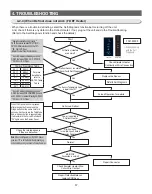
4-1-4) Restoration of Previous Settings upon Instant Power Outage
1) If the Display Panel is initialized by the instant power outage, it will cause customer inquiries.
To prevent this, when the power is restored, the previous settings will be restored or reset based on the
inside temperature of the unit.
2) Upon the initial power on, it checks its Freezer temperature. When it is lower than +5
℃
, it is to be
considered as an instant power failure and it brings back all its previous operation functions (Power
Freeze, Vacation, Fridge, Freezer, Alarm On, etc) related to the panel display.
3) When it is higher than +5
℃
, it is to be considered as a long-period power failure and it will initialize the
panel display. (Freezer: -20
℃
, Fridge: 3
℃
)
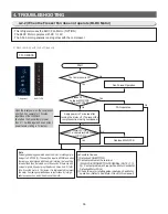
4-1-5) Demo Mode Function for Store Display
1) At the normal operation, press the F Alam buttons for 6 seconds.
Then, the Freezer and Fridge Temperature Display will blink in an interval of 0.5 second for 4 sec.
2) At this time, release the F Alam buttons and press the Fridge button (it sends out "Ding Dong"
sound.) Then, it shifts to the Demo Display mode.
3) When the unit is in Demo Mode, all the functions including the Display Panel works normal.
But, the Compressor and C-Fan do not operate.
4) To cancel the Demo Mode, Do the entering Demo mode again or turn off the power.
5) Aso, when the Freezer or Fridge room temperature goes over 65
℃
during the Demo Mode, the Demo
Mode will be cancelled and the unit will shift to the normal operation mode.
6) The initial real temperature display function will end.
②
①
Press the F Alarm
buttons for 6 seconds at the
same time, and while the Display
LEDs are blinking for 4 seconds,
release the buttons and
②
Press the Fridge button once.
BAR-TYPE
7-Segment
①
Summary of Contents for RL60GG Series
Page 75: ...75 5 PCB DIAGRAM 5 3 Connector Layout and Description Main Board 5 3 1 Q G J OPTION...
Page 76: ...76 5 PCB DIAGRAM 5 3 2 R P Z H Option...
Page 77: ...77 5 PCB DIAGRAM 5 3 3 L Option...
Page 78: ...78 5 PCB DIAGRAM 5 3 4 W E Option...
Page 80: ...80 5 PCB DIAGRAM IPM DIODE VOLTAGE 5 5 IPM Diode Voltage...
Page 81: ...81 6 WIRING DIAGRAM 6 1 Q G J OPTION...
Page 82: ...82 6 WIRING DIAGRAM 6 2 R P Z H Option...
Page 83: ...83 6 WIRING DIAGRAM 6 3 L Option...
Page 84: ...84 6 WIRING DIAGRAM 6 4 W E Option...
Page 85: ...85 6 WIRING DIAGRAM 6 5 S Option...
Page 86: ...86 7 CIRCUIT DIAGRAM 7 1 Schematic Diagram PBA Main 7 1 1 Q G J OPTION...
Page 87: ...87 7 CIRCUIT DIAGRAM 7 1 2 R P Z H L Option...
Page 88: ...88 7 CIRCUIT DIAGRAM 7 1 3 W E S Option...
Page 89: ...89 7 CIRCUIT DIAGRAM 7 2 Schematic Diagram PBA Inverter...
Page 90: ...90 7 CIRCUIT DIAGRAM 7 3 Block Diagram PBA Main...
Page 91: ...91 7 CIRCUIT DIAGRAM 7 4 Block Diagram PBA Inverter G H L P R Z Option...
Page 92: ...92 7 CIRCUIT DIAGRAM 7 5 Block Diagram PBA Inverter Q J Option...


