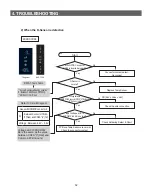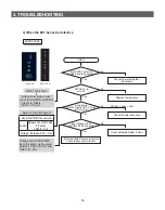
46
4. TROUBLESHOOTING
●
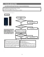
When the Display Panel converts to the Option Setting mode, the entire Display except the Fridge as
shown below Temp LED goes off.
1) For example, if you want to shift the standard temp of the Freezer compartment by -2
℃
, follow the steps
below. This function is to change the default temperature and when the default temperature of the
Freezer compartment is -20
℃
and the default setting is lowered by -2
℃
with the Option function, the
default temperature will be controlled at -22
℃
. That is, when changing temperature options, the Freezer
compartment will operate at -22
℃
internally even if it shows -20
℃
on the display panel.
Therefore, the temperature will be controlled by -2
℃
lower than the set temperature on the display panel.
2) After changing into the Option mode, “0"s on both of the Fridge and Freezer compartments lights up on
the display panel. (when units being shipped out, the unit will be shipped out with "0"s set on both of the
Fridge and Freezer compartments. However, for the purpose of quality improvement during mass
production, the Default values may change.)
- When only “0” lights up on the Fridge compartment, the Freezer temperature option can be set and the
current set Freezer temperature will show on the display panel.
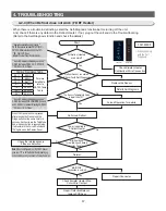
3) If the Freezer temp code is set to "4" as the following table after setting the Fridge section to "0", the
Freezer base temperature is to be lowered by -2
℃
(Refer to the Freezer temperature setting image.)
:In 15 seconds after completing the adjustment, MICOM is to store the setting value in EEPROM and it
goes back to the normal display mode, deactivating the Option Setting mode.
4) The Fridge temperature can be adjusted with the same method.
5) Make sure not to change the factory-set default values otherwise exception cases.
Also, the Option Setting is to be completed when it goes back to the normal display mode in 15 seconds.
So, do not turn off the unit before it goes back to the normal display mode.
Freezer Temp Setting
Fridge Temp Setting
Note Basically, when units being shipped out, all the data in the Option function are cleared. That is, the
Default settings are “0”. However, for the purpose of quality improvement during mass production, the
Default values may change. Therefore, be sure to check quality information, such as SVC bulletins.
Summary of Contents for RL60GG Series
Page 75: ...75 5 PCB DIAGRAM 5 3 Connector Layout and Description Main Board 5 3 1 Q G J OPTION...
Page 76: ...76 5 PCB DIAGRAM 5 3 2 R P Z H Option...
Page 77: ...77 5 PCB DIAGRAM 5 3 3 L Option...
Page 78: ...78 5 PCB DIAGRAM 5 3 4 W E Option...
Page 80: ...80 5 PCB DIAGRAM IPM DIODE VOLTAGE 5 5 IPM Diode Voltage...
Page 81: ...81 6 WIRING DIAGRAM 6 1 Q G J OPTION...
Page 82: ...82 6 WIRING DIAGRAM 6 2 R P Z H Option...
Page 83: ...83 6 WIRING DIAGRAM 6 3 L Option...
Page 84: ...84 6 WIRING DIAGRAM 6 4 W E Option...
Page 85: ...85 6 WIRING DIAGRAM 6 5 S Option...
Page 86: ...86 7 CIRCUIT DIAGRAM 7 1 Schematic Diagram PBA Main 7 1 1 Q G J OPTION...
Page 87: ...87 7 CIRCUIT DIAGRAM 7 1 2 R P Z H L Option...
Page 88: ...88 7 CIRCUIT DIAGRAM 7 1 3 W E S Option...
Page 89: ...89 7 CIRCUIT DIAGRAM 7 2 Schematic Diagram PBA Inverter...
Page 90: ...90 7 CIRCUIT DIAGRAM 7 3 Block Diagram PBA Main...
Page 91: ...91 7 CIRCUIT DIAGRAM 7 4 Block Diagram PBA Inverter G H L P R Z Option...
Page 92: ...92 7 CIRCUIT DIAGRAM 7 5 Block Diagram PBA Inverter Q J Option...


