57
4. TROUBLESHOOTING
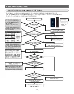
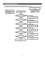
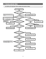
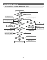
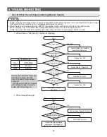
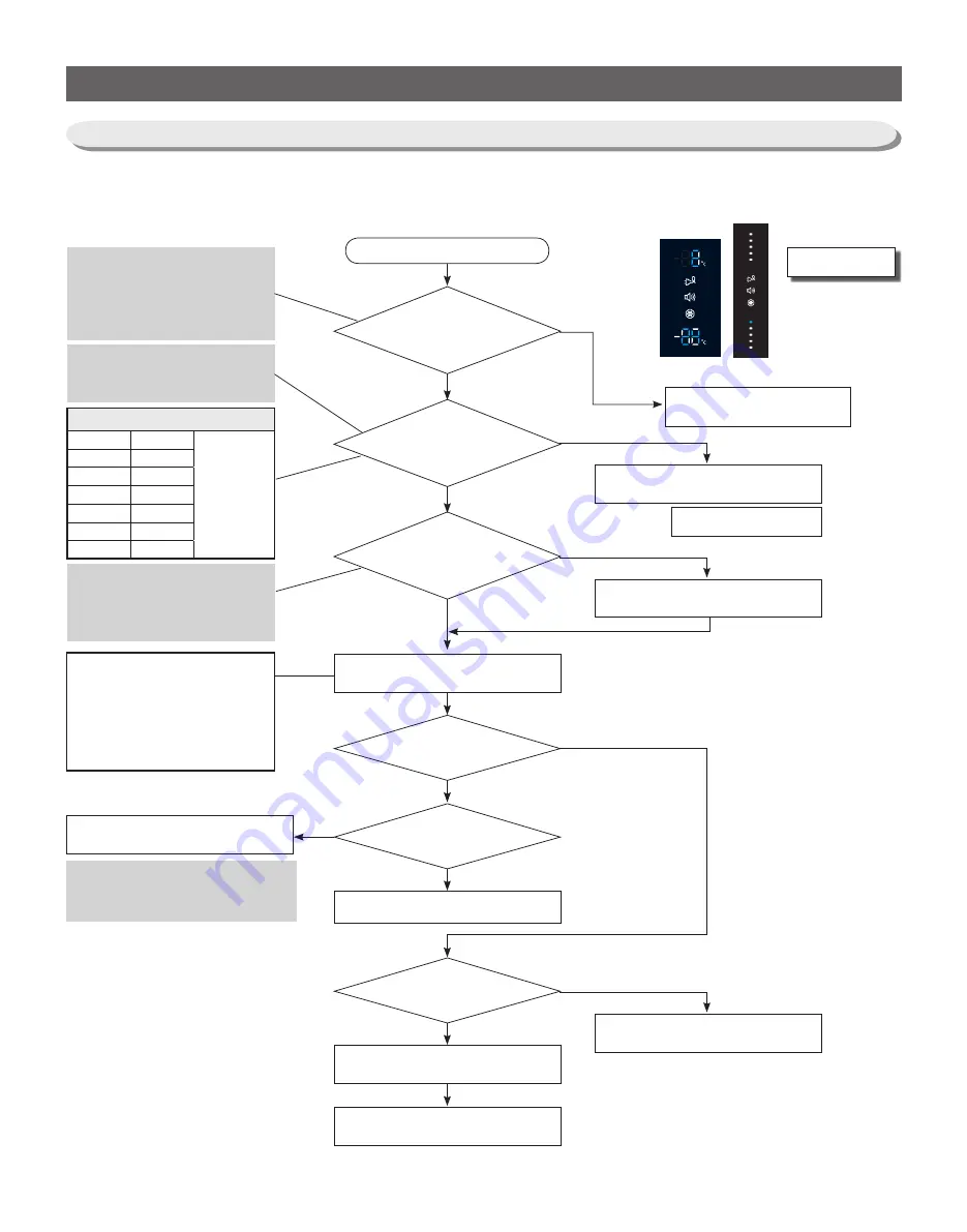
Defrost Sensor is normal?
(Check it with Self-Diagnosis)
The Sensor Temperature Value
is lower than 12
℃
.
After heating up
for a while, it goes back to
Cooling Operation
MAIN PCB
Connection is normal?
Power is applied to
F-Defrost Heater.
Start
Do Forced Defrost
Normal
Check Bimetal, Heater Wire
Cut or Wire Contact
Repair Defective Relay or
replace PCB Assy
Replace the Sensor
Forced Operation for a while
Repair Connector
Check the related sensors
if they are defective.
No
No
No
No
No
Yes
Yes
Yes
Yes
Yes
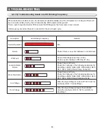
☞ When checking
with the Self
Diagnosis
F DEF. ERROR
Temp vs. Resistance Table
30
℃
4.22
㏀
For more
detail data,
refer to
DATA1. Temp
Table
20
℃
6.05
㏀
10
℃
8.87
㏀
0
℃
13.29
㏀
-10
℃
20.42
㏀
-20
℃
32.23
㏀
-30
℃
52.41
㏀
** Sensor Resistance Reading Location **
F-DEF : Between CN30 #4
↔
CN72 #10
** 0Ω : Short / ∞Ω : Open
** Sensor Resistance Reading Location **
F-DEF : Between PCB COMMON Ground
and CN30 #4 (or Sensor Marking #2(R302)
** 0Ω : Short / ∞Ω : Open
Note When the temperature of the F DEF Sensor
goes over 12
℃
with the Defrost Heater heating up,
it stops heating and it goes back to Cooling Operation.
When the Freezer button is pressed
after pressing the Freezer and the
Fridge buttons at the same time for 6
seconds, it will enter into the Test Mode.
And, when any button is pressed twice,
it will enter into the Forced Defrost and
"Fd" lights up on the Display Panel.
** Heater Resistance Reading Location **
F-DEF : Resistance between CN70 #1(BLK)
↔
CN70 #5 (White) should be 260 ohm ± 10%.
** 0Ω : Short / ∞Ω : Open
(Bimetal / Thermal Fuse / Heater Defect)
Refer to Self-Diagnosis
Check Bimetal, Heater
Continuity or Wire Connection
All Defrost Heaters
are normal?
Yes
No
4-2-4) When Defrost does not work (F DEF Heater)
- When there is a trouble in defrosting, select the Self-Diagnosis function before turning off the unit.
And, check if there is any defect in the Defrost Heater. If not, plug out the unit and do the Trouble-Shooting.
(Refer to the Self-Diagnosis function and check the details)
BAR-TYPE
7-Segment
Summary of Contents for RL60GG Series
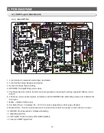
Page 75: ...75 5 PCB DIAGRAM 5 3 Connector Layout and Description Main Board 5 3 1 Q G J OPTION...
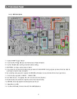
Page 76: ...76 5 PCB DIAGRAM 5 3 2 R P Z H Option...
Page 77: ...77 5 PCB DIAGRAM 5 3 3 L Option...
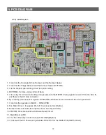
Page 78: ...78 5 PCB DIAGRAM 5 3 4 W E Option...
Page 80: ...80 5 PCB DIAGRAM IPM DIODE VOLTAGE 5 5 IPM Diode Voltage...
Page 81: ...81 6 WIRING DIAGRAM 6 1 Q G J OPTION...
Page 82: ...82 6 WIRING DIAGRAM 6 2 R P Z H Option...
Page 83: ...83 6 WIRING DIAGRAM 6 3 L Option...
Page 84: ...84 6 WIRING DIAGRAM 6 4 W E Option...
Page 85: ...85 6 WIRING DIAGRAM 6 5 S Option...
Page 86: ...86 7 CIRCUIT DIAGRAM 7 1 Schematic Diagram PBA Main 7 1 1 Q G J OPTION...
Page 87: ...87 7 CIRCUIT DIAGRAM 7 1 2 R P Z H L Option...
Page 88: ...88 7 CIRCUIT DIAGRAM 7 1 3 W E S Option...
Page 89: ...89 7 CIRCUIT DIAGRAM 7 2 Schematic Diagram PBA Inverter...
Page 90: ...90 7 CIRCUIT DIAGRAM 7 3 Block Diagram PBA Main...
Page 91: ...91 7 CIRCUIT DIAGRAM 7 4 Block Diagram PBA Inverter G H L P R Z Option...
Page 92: ...92 7 CIRCUIT DIAGRAM 7 5 Block Diagram PBA Inverter Q J Option...


