17
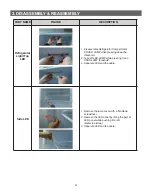
3. DISASSEMBLY & REASSEMBLY
3-3) Door Sub parts
PART NAME
FIGURE
DESCRIPTION
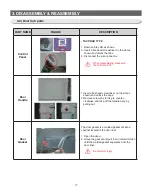
Control
Panel
- TACT/BAR TYPE
1. Remove inlay film as shown.
2. Insert a flat-head screwdriver on the slot as
shown,and unlock the tabs.
3. Disconnect the wire connector.
When diassembling, make sure
the unit turned off.
Door
Handle
1. Insert a flat-head screwdriver on the slot as
shown,and unlock the caps.
2. Remove screws by turning to counter-
clockwise,and take off the Handle Assy by
pulling out.
Door
Gasket
The door gasket is a molded gasket set into a
channel located in the door liner.
1. Open the doovr.
2. Grasp the gasket and pull in an outward motion
until the molded gasket separates from the
door liner.
Be careful of injury.
Summary of Contents for RL60GG Series
Page 75: ...75 5 PCB DIAGRAM 5 3 Connector Layout and Description Main Board 5 3 1 Q G J OPTION...
Page 76: ...76 5 PCB DIAGRAM 5 3 2 R P Z H Option...
Page 77: ...77 5 PCB DIAGRAM 5 3 3 L Option...
Page 78: ...78 5 PCB DIAGRAM 5 3 4 W E Option...
Page 80: ...80 5 PCB DIAGRAM IPM DIODE VOLTAGE 5 5 IPM Diode Voltage...
Page 81: ...81 6 WIRING DIAGRAM 6 1 Q G J OPTION...
Page 82: ...82 6 WIRING DIAGRAM 6 2 R P Z H Option...
Page 83: ...83 6 WIRING DIAGRAM 6 3 L Option...
Page 84: ...84 6 WIRING DIAGRAM 6 4 W E Option...
Page 85: ...85 6 WIRING DIAGRAM 6 5 S Option...
Page 86: ...86 7 CIRCUIT DIAGRAM 7 1 Schematic Diagram PBA Main 7 1 1 Q G J OPTION...
Page 87: ...87 7 CIRCUIT DIAGRAM 7 1 2 R P Z H L Option...
Page 88: ...88 7 CIRCUIT DIAGRAM 7 1 3 W E S Option...
Page 89: ...89 7 CIRCUIT DIAGRAM 7 2 Schematic Diagram PBA Inverter...
Page 90: ...90 7 CIRCUIT DIAGRAM 7 3 Block Diagram PBA Main...
Page 91: ...91 7 CIRCUIT DIAGRAM 7 4 Block Diagram PBA Inverter G H L P R Z Option...
Page 92: ...92 7 CIRCUIT DIAGRAM 7 5 Block Diagram PBA Inverter Q J Option...


