102
Setting the MCU and Pipe Addresses (for HR Only)
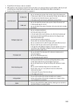
2. When the Auto pipe pairing operation finishes, the following data is shown on the outdoor unit display.
Result
Outdoor unit display
Description
Setting completed
End
Setting error
E191
Indoor unit data
(displayed alternately)
Indoor unit data
- SEG 1,2 = indoor unit address / SEG 3,4 = error status
00: An MCU port is not
disabled, or a pipe is not
connected.
01: Cooling only indoor unit is
connected to MCU.
02: The shared setting for two
ports is incorrect.
Example) When the MCU port connected to the indoor unit 12 is
disabled, E191 and 1200 are displayed alternately
- If two or more indoor units have setting errors, the data about the next
indoor unit is displayed each time you press the K2 switch.
• If the MCU ports to use are set incorrectly, the Auto pipe pairing operation may stop due to high-pressure or low-
pressure protection control or the data about the indoor unit that has a MCU port setting error may be incorrect. Ensure
that the MCU ports to use are set correctly.
• Depending on the indoor and outdoor temperatures, the Auto pipe pairing operation may stop due to protection
control.
• If an error occurs while the Auto pipe pairing operation is running, check the error code and take actions.
• If you cannot finish the Auto pipe pairing operation because of the previous reasons, set the pipe addresses manually by
referring to Setting the Pipe Addresses Manually.
CAUTION
Things to check after completing the installation
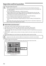
1. Before supplying the power, use DC 500 V insulation resistance tester to measure the power (3 phase: R, S, T/ 1 phase: L,
N) terminal and the outdoor unit grounding.
- Measurement should be over 30MΩ.
2. Before supplying the power, use a voltmeter and phase tester to check the voltage and the phase.
- R, S, T, N terminal: check if the voltage is within 380-415 V between wires (R-S, S-T, T-R) and 200-240 V between phases
(R-N, S-N, T-N) before turning on the switch.
• Never measure the communication terminal since communication circuit may get damaged.
• Check for short-circuit of the communication terminal with a general circuit tester.
CAUTION
N
T
S
R
< ELB >
230V
400V
400V
400V
230V
230V
Summary of Contents for DVM S AM080FXVAGH
Page 112: ......


