background image

Troubleshooting

4-24

Samsung Electronics

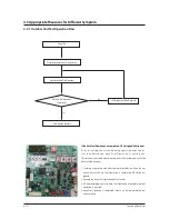
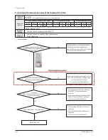
4-3-4  Communication Error between Indoor and Outdoor Units after Tracking

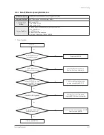
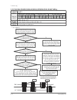
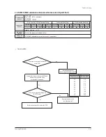
1.  Cause of problem

Press the reset key (K3) of the outdoor unit PCB  

and check the display module.

Is the voltage between  

the 2 cables a square wave with DC±0.7V or more  

as shown in the image below?

Is there no indoor unit  

response at all from the display module during  

the tracking?

Remove the communication cable that connects  

the outdoor unit to the indoor nit, and measure 

 the 2 outdoor unit cables with a scope.

Connect the communication cable again to  

connect the outdoor unit to the indoor unit.

Remove all the communication connectors on the PCB of  

the indoor unit, and connect them one by one to find  

the indoor unit which interferes with the communication  

to check and change the indoor unit PCB.

After two minutes, find the indoor unit which displays the 

communication error and check if the PCB address settings are 

overlapped. (Communication error occurs if the indoor unit  

addresses are overlapped.)- In this case, the communication 

error will occur in every indoor unit (2 or more units) with the 

address incorrectly set.

Check the communication cable and the 

connector for the outdoor unit PCB,  

and change the PCB.

0.7V

0.7V

Good

Defective

If there is no peculiarity in the address, check  

the communication cable and change the indoor unit PCB.

Yes

No

No

Yes

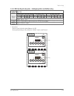
* Essential Requirements before Changing PCB in 
Case of Communication Error: Refer to p.50

Outdoor unit 

display

Indoorunit 

display

Duct, Cassette (1/2 Way),Console, Celing

Cassette (4/Mini4 Way)

Wall-mounted (NeoForte)

Operation Defrost Timer Fan Filter/MPI Operation Defrost Timer Filter Operation Timer Turbo 24

27

×

×

×

×

×

×

×

※ ●

: ON   

: Flash   ×: OFF

Judgment 

Method

∙  Outdoor unit is unable to communicate for two minutes during operation. (no reception of relocation)

Cause of 

problem

∙  Communication error between indoor and outdoor units and setup error of indoor unit installation quantity setup switch.

Summary of Contents for DVM S AM080FXVAGH

Page 1: ... 2606XV666 AM080 100 120 200FXWA666 AM080 100 120 140 160 180 200 220JXVA66 AM140 160 180 200 220 240 260 280 300KXV666 1 Precautions 2 Product Specifications 3 Disassembly and Reassembly 4 Troubleshooting 5 PCB Diagram and Parts List 6 Wiring Diagram 7 Cycle Diagram 8 Key Options 9 TestOperation ...

Page 2: ...3 2 3 2 1 AM080 100 120JXV666 3 2 3 2 2 AM140FXVAGH AM140JXV6GH 3 12 3 2 3 AM160 180 200 220 240 2606XV666 AM140JXVA6H 3 22 3 2 4 AM080 100 120FXWA66 3 33 3 2 5 AM200FXWA66 3 41 3 2 6 AM140 160KXVG66 AM140 160 180KXVA66 3 48 3 2 7 AM180 200 220KXVG66 AM200 220KXVA66 3 55 3 2 8 AM240 260 280 300KXV666 AM080KXVS66 3 63 3 3 Caution at compressor exchange 3 72 3 4 MCU 3 77 3 5 EEV KIT 3 78 4 Troublesh...

Page 3: ...r Open Short 4 49 4 3 28 EVI Out Temperature sensor error Open Short 4 50 4 3 29 Suction 2 Temperature Sensor Error Open Short 4 51 4 3 30 Measures of other outdoor unit error 4 52 4 3 31 E407 Comp Down due to High Pressure Protection Control 4 53 4 3 32 E410 Comp Down due to Low Pressure Protection Control 4 55 4 3 33 E416 Suspension of starting due to Compressure discharge temperature sensor Top...

Page 4: ...300KXVA66 AM080KXVS66 7 5 7 11 AM180 200 220KXVG66 AM200 220KXVA66 7 6 7 12 AM140 160KXVG66 AM140 160 180KXVA66 7 6 7 13 Cooling operation H R 7 6 7 14 Main cooling operation H R 7 7 7 15 Heating operation H R 7 8 7 16 Main heating operation H R 7 9 7 17 Cooling operation H P 7 10 7 18 Heating operation H P 7 11 7 19 Cooling operation H R AM080 100 120 200FXWA66 7 12 7 20 Main cooling operation H ...

Page 5: ...atic electricity Please wear insulation gloves before performing PCB repair and measurement O Check if the place of installation is at least 2m away from electronic appliances such as TV video players and stereos This can cause irregular noise or degrade the picture quality O Please make sure the customer does not directly repair the product Arbitrary dismantling may result in electric shock or fi...

Page 6: ...a danger to workers O Please remove the oxide produced inside the pipe during the welding with nitrogen gas Using another gas may cause harm to the product or others 1 6 Precautions for Additional Supplement of Air Conditioner Refrigerant O Precisely calculate the refrigerant by using a scale and S net and proceed with the test operation Excessive supplement can cause harm to the product since it ...

Page 7: ...14 160Hz driving 3 generation Vapor Injection Performance maximization of low temperature heating DSI System High Pressure Refrigerant Outlet Medium Pressure Refrigerant Injection Low Pressure Refrigerant Inlet Low Pressure Refrigerant Inlet 3 generation Vapor Injection 3 generation Vapor Injection Low Pressure Refrigerant Inlet High Pressure Refrigerant Outlet High Pressure Refrigerant Outlet Med...

Page 8: ...thod When natural convection electric heat performance is low and is high load efficiency is fallen Refrigerant cooling system Forced circulation electric heat performance is high and control of thermal conductivity is 10 times higher than air load is available Coolingof invertercircuit Refrigerant cooling system It is cooling technology of inverter circuit that use refrigerating cycle technology ...

Page 9: ...erstructureࣖDouble LayerStructure Invertertechnologyintegration Invertercontrolcircuit composition C Boxvolumemaximumuse Built intypeControllerembodi ment Integratedpowersupply controlunit Pipingserviceeasiness Q Control Box PCB Changed part Changeditem andfeature Basic Afterchanged CABINET Changethecolor TOUCHGRAY ࣖEARTHBROWN WireHarnessinstallationpart change LOGOchange ...

Page 10: ...eplace needoption download HubPCB HubPCBnewlyapplication Separationforload control Enhancedfixingofload sensorwire FANPCB Usecontrollerof3phasepower Preventedphaseunbalance TemperatureprotectionofIPM InverterPCB Compressor ControlPCB AppliedinverterCompressor Refrigerantcoolingmethod MountpowerrelayonPCB EMIPCB 3phasepowerEMIPCB Fusemount Communication Terminalblock Mountcommunicationterminalblock...

Page 11: ...HubPCB HubPCBnewlyapplication Separationforload control Enhancedfixingofload sensorwire FANPCB Usecontrollerof3phasepower Preventedphaseunbalance TemperatureprotectionofIPM InverterPCB Compressor ControlPCB AppliedinverterCompressor Refrigerantcoolingmethod MagnetS W ױ DidPowerRelaymounttoPCB EMIPCB 3phasepowerEMIPCB Fusemount Communication Terminalblock DidCommunicationTerminalblock mounttoPCB Wa...

Page 12: ... high capacity compressor Increases capacitor s capacity Applies EMI coil on board Deletes core in wire EMI PCB Develops 50A EMI PBA ױ Increases coil size and fuse capacity Improves EMI characteristic REACTOR Increases current due to high capacity compressor Improved wire connection terminal Refrigerant cooling Increases heat cooling capacity Increases pipe size and heat exchange area Changes in c...

Page 13: ...art Changed item and feature Basic After changed Pipe Cooling New Pipe Cooling for cooling of inverter PCB Unapplied COOLING OF INVERTER CIRCUIT REFRIGERANT COOLING SYSTEM IT IS COOLING TECHNOLOGY OF INVERTER CIRCUIT THAT USE REFRIGERATING CYCLE TECHNOLOGY COOLING OF INVERTER CIRCUIT Q PIPE COOLING ...

Page 14: ...2 8 Samsung Electronics Changed part Changeditem andfeature Basic Afterchanged HP Afterchanged HR Tube struc ture New inverter cycle technol ogy application New piping Q TUBE ...

Page 15: ...Samsung Electronics 2 9 2 1 3 Structure of product Heat Pump AM6666XV66H Series Small size Large size ...

Page 16: ... Large size Heat exchanger CONTROL BOX 4 WAY V V Intercooler Accumulator Low Pressure Gas Pipe Oil separator Compressor High Pressure Gas Pipe Liquid pipe Heat exchanger 4 WAY V V Accumulator Intercooler Low Pressure Gas Pipe High Pressure Gas Pipe Liquid pipe Compressor Oil separator CONTROL BOX ...

Page 17: ...t Power supply for 460V 60Hz 3Φ AM6666XV66J6 Series Small size Large size CONTROL BOX 4 WAY V V Oil separator Heat exchanger Sub Cooler Compressor CONTROL BOX 4 WAY V V Accumulator Compressor Oil separator Heat exchanger Sub Cooler TRANS BOX TRANS BOX ...

Page 18: ... WAY V V Accumulator CONTROL BOX Oil separator Compressor High pressure Gas Pipe Low pressure Gas Pipe Sub Cooler Plate Heat Exchanger Receiver CONTROL BOX Liquid Pipe High pressure Gas Pipe Low pressure Gas Pipe 4 WAY V V Receiver Plate Heat Exchanger Accumulator Sub Cooler Compressor Oil separator ...

Page 19: ...M666KX6 Series AM140 160KXVG66 AM140 160 180KXVA66 AM180 200 220KXVG66 AM200 220KXVA66 Control Box Compressor Liquid V V Gas V V Subcooler Accumulator 4 WAY V V Heat Exchanger Control Box Control Box Liquid V V Gas V V Subcooler Accumulator 4 WAY V V Heat Exchanger ...

Page 20: ...14 Samsung Electronics Structure of product Heat Pump AM666KX6 Series AM240 260 280KXVG66 AM240 260 280 300KXVA66 AM080KXVS66 Heat Exchanger Compressor CONTROL BOX 4 WAY V V Subcooler Gas Pipe Liquid Pipe ...

Page 21: ...70 9 52 9 52 12 70 Ø inch 3 8 3 8 1 2 Gas Ø mm 19 05 22 22 28 58 19 05 22 22 25 40 Ø inch 3 4 7 8 1 1 8 Dis Gas Ø mm 15 88 19 05 19 05 Ø inch 5 8 3 4 3 4 Installation Limitation Max Length m 200 220 200 220 200 220 200 200 200 Max Height m 110 40 110 40 110 40 50 40 50 40 50 40 Cable MainPower Below about20m mm2 4 0 4 0 4 0 1 5 2 5 4 0 Communication mm2 VCTF 0 75 1 5 2P VCTF 0 75 1 5 2P VCTF 0 75 ...

Page 22: ...s Ø mm 19 05 22 22 Ø inch 3 4 7 8 Installation Limitation Max Length m 200 220 200 220 200 200 Max Height m 110 40 110 40 50 40 50 40 Cable MainPower Below about20m mm2 4 0 6 0 4 0 6 0 Communication mm2 VCTF0 75 1 5 2P VCTF0 75 1 5 2P VCTF0 75 1 5 2P VCTF0 75 1 5 2P Set Dimension NetWeight DVM S HP kg 235 0 278 0 280 329 DVM S HR 214 0 184 0 Shipping Weight DVM S HP kg 254 0 297 0 301 350 DVM S HR...

Page 23: ...s Ø mm 28 58 28 58 28 58 28 58 28 58 Ø inch 1 1 8 1 1 8 1 1 8 Dis Gas Ø mm 22 22 28 58 28 58 Ø inch 7 8 1 1 8 1 1 8 Installation Limitation Max Length m 200 220 200 220 200 220 200 200 Max Height m 110 40 110 40 110 40 50 40 50 40 Cable MainPower Below about20m mm2 10 0 10 0 10 0 6 0 10 0 Communication mm2 VCTF 0 75 1 5 2P VCTF 0 75 1 5 2P VCTF 0 75 1 5 2P VCTF 0 75 1 5 2P VCTF 0 75 1 5 2P Set Dim...

Page 24: ...8 1 2 Gas Ø mm 19 05 22 22 28 58 19 05 22 22 25 40 Ø inch 3 4 7 8 1 1 8 Dis Gas Ø mm 15 88 19 05 19 05 15 88 19 05 22 22 Ø inch 5 8 3 4 3 4 Installation Limitation Max Length m 200 220 200 220 200 220 200 200 200 Max Height m 110 40 110 40 110 40 50 40 50 40 50 40 Cable MainPower Below about20m mm2 4 0 4 0 4 0 1 5 2 5 4 0 Communication mm2 VCTF0 75 1 5 2P VCTF0 75 1 5 2P VCTF0 75 1 5 2P VCTF0 75 1...

Page 25: ... 19 05 22 22 22 22 25 40 Ø inch 3 4 7 8 Installation Limitation Max Length m 200 220 200 220 200 200 Max Height m 110 40 110 40 50 40 50 40 Cable MainPower Below about20m mm2 4 0 6 0 4 0 6 0 Communication mm2 VCTF0 75 1 5 2P VCTF0 75 1 5 2P VCTF0 75 1 5 2P VCTF0 75 1 5 2P Set Dimension NetWeight DVM S HP kg 235 0 278 0 293 338 DVM S HR 214 0 184 0 Shipping Weight DVM S HP kg 254 0 297 0 314 359 DV...

Page 26: ...8 28 58 28 58 Ø inch 1 1 8 1 1 8 1 1 8 Dis Gas Ø mm 22 22 28 58 28 58 28 58 28 58 Ø inch 7 8 1 1 8 1 1 8 Installation Limitation Max Length m 200 220 200 220 200 220 200 200 Max Height m 110 40 110 40 110 40 50 40 50 40 Cable MainPower Below about20m mm2 10 0 10 0 10 0 6 0 10 0 Communication mm2 VCTF0 75 1 5 2P VCTF0 75 1 5 2P VCTF0 75 1 5 2P VCTF0 75 1 5 2P VCTF0 75 1 5 2P Set Dimension NetWeight...

Page 27: ... 1 5 50 5 20 5 20 5 20 Nominal Heating 2 6 00 5 80 5 80 5 80 Compressor Type SSC Scroll x 1 SSC Scroll x 1 SSC Scroll x 1 SSC Scroll x 2 DVI Scrollx1 DVI Scrollx1 FVI Scrollx1 DVI Scroll FVI Scrollx2 Output kW 4 96 4 96 6 13 4 96 x 2 7 04 7 48 7 43 7 48 7 43 x 2 Oil Type PVE PVE PVE PVE 3MAF POE 3MAF POE 3MAF POE Initial Charge Liter 3 9 3 9 3 9 6 2 2 185 4 37 6 555 Condenser Type Stainless steel ...

Page 28: ...0 Cable MainPower Below20m mm2 16 16 Communication mm2 VCTF0 75 1 5 2P VCTF0 75 1 5 2P Set Dimension Net weight kg 360 360 Gross weight kg 370 370 Net dimension WxHxD mm 1 295 x 1 695 x 765 1 295 x 1 695 x 765 Gross dimension WxHxD mm 1 363 x 1 887 x 832 1 363 x 1 887 x 832 OperatingTemp Range Cooling ఁ 5 0 48 0 5 0 48 0 Heating ఁ 25 0 24 0 25 0 24 0 Outdoor Unit cont 1 Proper form capacity standa...

Page 29: ... 25 0 32 0 39 1 22 30 44 5 Power Consumption Cooling kW 5 00 6 85 8 16 10 93 11 98 12 45 14 59 17 35 Heating kW 5 10 6 65 8 03 10 15 11 60 11 90 13 90 16 70 MCA MFA A 22 5 30 29 9 40 31 3 40 31 3 40 40 0 40 48 9 50 52 5 75 55 6 75 COP Nominal Cooling 4 480 4 090 4 120 3 660 3 760 4 050 3 840 3 550 Nominal Heating 4 940 4 740 4 710 4 430 4 340 4 760 4 530 4 150 ESEER HP Compressor Model DS GA046FA ...

Page 30: ...25 0 32 0 39 1 42 5 44 5 Power Consumption Cooling kW 4 59 6 22 7 57 10 55 10 92 11 51 13 05 15 75 Heating kW 4 59 5 89 7 56 9 72 10 75 11 62 13 10 15 86 MCA MFA A 22 5 30 29 9 40 31 3 40 31 3 40 40 0 40 48 9 50 52 5 75 55 6 75 COP Nominal Cooling 4 880 4 500 4 440 3 790 4 120 4 380 4 290 3 910 Nominal Heating 5 490 5 350 5 000 4 630 4 690 4 880 4 810 4 370 ESEER HP Compressor Model DS GB052FA DS ...

Page 31: ...Cooling kW 4 59 6 22 7 57 10 55 10 92 11 51 13 05 15 75 Heating kW 4 59 5 89 7 56 9 72 10 75 11 62 13 10 15 86 MCA MFA A 22 5 30 29 9 40 31 3 40 31 3 40 40 0 40 48 9 50 52 5 75 55 6 75 COP Nominal Cooling 4 880 4 500 4 440 3 790 4 120 4 380 4 290 3 910 Nominal Heating 5 490 5 350 5 000 4 630 4 690 4 880 4 810 4 370 ESEER HP Compressor Model DS GB052FA DS GB066FA DS GB066FA DS GB066FA DS GA046FA DS...

Page 32: ... 91 5 11 4 90 4 89 5 45 4 96 5 68 5 91 5 11 4 90 4 89 5 45 4 96 4 39 Compressor Type ScrollInverter ScrollInverter ScrollInverter ScrollInverter ScrollInverter ScrollInverter ScrollInverter ScrollInverter ScrollInverter ScrollInverter ScrollInverter ScrollInverter ScrollInverter ScrollInverter ScrollInverter Output kW n 5 18x1 6 45x1 6 45x1 5 18x2 5 18x2 6 45x2 6 45x2 4 39x1 6 39x1 6 39x1 4 39x2 4...

Page 33: ... 0 21 1 25 25 0 32 0 39 1 22 30 44 5 Power Consumption Cooling kW 5 00 6 85 8 77 10 93 11 98 12 45 14 59 17 35 Heating kW 5 10 6 65 9 3 10 15 11 60 11 90 13 90 16 70 MCA MFA A 22 5 30 29 9 40 31 3 40 31 3 40 40 0 40 48 9 50 52 5 75 55 6 75 COP Nominal Cooling 4 480 4 090 3 83 3 660 3 760 4 050 3 840 3 550 Nominal Heating 4 940 4 740 4 06 4 430 4 340 4 760 4 530 4 150 ESEER HP Compressor Model DS G...

Page 34: ... 89 10 92 10 68 12 50 15 75 16 00 17 33 19 65 4 26 Heating kW 9 62 10 75 10 52 12 75 15 86 15 43 17 06 18 77 4 38 MCA MFA A 25 0 40 32 0 40 39 2 50 42 0 75 44 6 75 55 0 75 60 0 75 67 0 75 29 0 40 COP NominalCooling 4 500 4 120 4 720 4 480 3 910 4 200 4 200 4 000 5 260 NominalHeating 4 680 4 690 5 390 4 940 4 370 4 900 4 800 4 700 5 750 ESEER HP Compressor Model DS GB066FA DS4G 5080F DS GB066FA DS ...

Page 35: ...kW 10 93 12 10 12 60 14 18 17 35 17 10 18 91 20 68 22 70 Heating kW 10 16 11 61 11 91 13 91 16 70 17 42 18 00 20 18 20 59 MCA MFA A 25 0 40 32 0 40 39 2 50 42 0 75 44 6 75 55 0 75 60 0 75 67 0 75 73 0 90 COP NominalCooling 3 660 3 720 4 000 3 950 3 550 3 930 3 850 3 800 3 700 NominalHeating 4 430 4 340 4 760 4 530 4 150 4 340 4 550 4 370 4 590 ESEER HP Compressor Model DS GB066FA DS4G 5080F DS4G 5...

Page 36: ... 0 44 6 55 0 60 0 67 0 Power Consumption Cooling kW 8 89 10 92 10 68 12 50 15 75 16 00 17 33 19 65 Heating kW 9 62 10 75 10 52 12 75 15 86 15 43 17 06 18 77 MCA MFA A 25 0 40 32 0 40 39 2 50 42 0 60 44 6 60 55 0 75 60 0 75 67 0 75 COP NominalCooling 4 500 4 120 4 720 4 480 3 910 4 200 4 200 4 000 NominalHeating 4 680 4 690 5 390 4 940 4 370 4 900 4 800 4 700 ESEER HP Compressor Model DS GB066FA DS...

Page 37: ...kW 10 93 12 10 12 60 14 18 17 35 17 10 18 91 20 68 22 70 Heating kW 10 16 11 61 11 91 13 91 16 70 17 42 18 00 20 18 20 59 MCA MFA A 25 0 40 32 0 40 39 2 50 42 0 60 44 6 60 55 0 60 60 0 75 67 0 75 73 0 90 COP NominalCooling 3 660 3 720 4 000 3 950 3 550 3 930 3 850 3 800 3 700 NominalHeating 4 430 4 340 4 760 4 530 4 150 4 340 4 550 4 370 4 590 ESEER HP Compressor Model DS GB066FA DS4G 5080F DS4G 5...

Page 38: ...33 20 36 40 24 80 27 40 Heating A 27 90 28 90 32 40 33 00 25 30 27 90 Max A 55 0 60 0 67 0 73 0 57 1 63 3 Power Consump tion Cooling kW 17 10 18 91 20 68 22 70 15 50 17 10 Heating kW 17 42 18 00 20 18 20 59 15 80 17 42 MCA MFA A 55 0 75 60 0 75 67 0 75 73 0 90 57 1 75 63 3 75 COP NominalCooling 3 930 3 850 3 800 3 700 3 970 3 930 NominalHeating 4 340 4 550 4 370 4 590 4 390 4 340 ESEER HP Compress...

Page 39: ...ow MXJ YA3100M Over70 3kW 135 2kWandbelow MXJ YA3800M Over135 2kW Distribution header MXJ HA2512M 45 0kWandbelow for4rooms MXJ HA3115M 70 3kWandbelow for8rooms MXJ HA3819M Over70 3kW 135 2kWand below for8rooms Y Joint Outdoor Unit MXJ TA3419M 135 2kWandbelow MXJ TA4122M Over140 2kW Y Joint Only H R Outdoor Unit MXJ TA3100M 135 2kWandbelow MXJ TA3800M Over140 2kW MCU Mode Control Unit MCU S6NEE1N 6...

Page 40: ...ly O For disassembly and assembly DVM PLUS indoor unit please refer to the products with the same structures Only those products that are not specified elsewhere are described here Item Remark SCREW DRIVER MONKEY SPANNER SCREW DRIVER NIPPER ELECTRIC MOTION DRIVER L WRENCH ...

Page 41: ...ctrical equipmentPart 1 Remove14screwsfromthecabinet Use screwdriver 2 Remove4screwsandseparatecovercontrol box Use screwdriver 3 Power Compressor Valve Motor Sensorcon nectorconnectedtoASSYPCBremove 3 2 Disassembly and Reassembly 3 2 1 AM080 100 120JXV666 ...

Page 42: ...s Procedure Remark 4 2screwshadfixedinterminalblockcover whenchangepowerterminalblockthen communicationterminalblockremove 5 2screwshadfixedinterminalblockafter remove4screwshadfixedtoCabinetforter minalblockprotectionremove 6 5screwshadfixedtoFrontpartremove ...

Page 43: ...ics 3 4 No Parts Procedure Remark 7 6screwshadfixedonsiderefrigerantcooling partoutsideremove DonotseparateHeatSinkpullingAssy PipingCoolingpipingcompulsorily Itcanbeacauseofpartsdamage 8 2screwshadfixedonsiderefrigerantcooling partinsideremove ...

Page 44: ...ionSensor EVIOutSensor INSULATION No Model InsuCode BindingWire AM080 100 120JXV66H DB62 04154C AM080 100 120JXV66H DB62 03808B AM080 100 120JXV66H DB62 03808C VALVE SENSOR No Valve Sensor ExpansionValve EVIEEVValve AccumOilReturnValve EVIInSensor INSULATION No Model InsuCode BindingWire AM080 100 120JXV66H DB62 03808C AM080 100 120JXV66H DB62 03808E ...

Page 45: ...0JXV66H VALVE SENSOR No Valve Sensor CompTop Sensor Discharge Sensor High Pressure Switch INSULATION No Model InsuCode BindingWire AM080 100 120JXV66H DB62 03808D VALVE SENSOR No Valve Sensor Low Pressure Sensor VALVE SENSOR No Valve Sensor Cond Out Sensor OutdoorTemperature Sensor ...

Page 46: ...suCode BindingWire AM080 100 120JXVHGR DB62 03808E AM080 100 120JXVHGR DB62 04154B AM080 100 120JXVHGR DB62 03808C VALVE SENSOR No Valve Sensor 4WAYValve HighPressureSensor Suciton1Sensor Suciton 2 Sensor EVI Out Sensor Main Cooling Valve EVI Bypass Valve EVI SOL Valve INSULATION No Model InsuCode BindingWire AM080 100FXVAGR AM080 100JXVHGR DB62 03808B AM120FXVAGR AM120JXVHGR DB62 03808G AM080 100...

Page 47: ...VHGR VALVE SENSOR No Valve Sensor CompTopSensor DischargeSensor HighPressureSwitch INSULATION No Model InsuCode BindingWire AM080 100 120JXVHGR DB62 03808D VALVE SENSOR No Valve Sensor LowPressureSensor EVI EEV Valve VALVE SENSOR No Valve Sensor CondOutSensor OutdoorTemperature Sensor ...

Page 48: ...g Electronics ـ CompWire fix by HolderWire ـ Fix CompWire Core to Bracket Beam Control Box using large size CableTie 350mm ـ Separate double layer structure of C Box after remove 3 screws and connector Binding Wire 3 غ AM080 100 120JXV666 ...

Page 49: ...g Subcooler 1 2 Comp Discharge 1 2 Subcooler EVI Bypass 1 3 Comp VaporInjection 1 3 Accum 4Way 1 4 Discharge OilSepa 1 4 Accum Accum OilVavle 1 5 4Way OilSepaOut 1 5 Accum EVI Bypass 1 6 OilReturn Suction 1 6 Vapor Injection EVI Bypass 1 7 HotGasVavle Suction 1 7 Hot GasVavle Oil Sepa Out 1 8 Expansion Subcooler 1 8 4Way Cond In 9 PinchPipe 1 9 Expansion Cond Out 10 AccumOilReturnValve Suction 1 1...

Page 50: ...g Subcooler 1 2 Comp Discharge 1 2 Subcooler EVI Bypass 1 3 Comp VaporInjection 1 3 Accum 4Way 1 4 Discharge OilSepa 1 4 Accum Accum OilVavle 1 5 4Way OilSepaOut 1 5 Accum EVI Bypass 1 6 4Way CondIn 1 6 Vapor Injection EVI Bypass 1 7 Expansion CondOut 1 7 Hot GasVavle Oil Sepa Out 1 8 PinchPipe 1 8 Oil Return Suction 9 AccumOilReturnValve Suction 1 9 LQD BallValve Subcooler 10 Subcooler Expansion ...

Page 51: ... 2 AM140FXVAGH AM140JXV6GH No Parts Procedure Remark 1 Electrical equipmentPart 1 Remove11screwsfromthecabinet Use screwdriver 2 Remove4screwsandseparatecovercontrol box Use screwdriver 3 Power Compressor Valve Motor Sensorcon nectorconnectedtoASSYPCBremove ...

Page 52: ...rts Procedure Remark 4 2screwshadfixedinterminalblockcover whenchangepowerterminalblock commu nicationterminalblockremove 5 2screwshadfixedinterminalblockafter remove4screwshadfixedtoCabinetforter minalblockprotectionremove 6 5screwshadfixedtoFrontpartremove ...

Page 53: ...ics 3 14 No Parts Procedure Remark 7 6screwshadfixedonsiderefrigerantcooling partoutsideremove DonotseparateHeatSinkpullingAssy PipingCoolingpipingcompulsorily Itcanbeacauseofpartsdamage 8 2screwshadfixedonsiderefrigerantcooling partinsideremove ...

Page 54: ...ENSOR No Valve Sensor 4WAYValve HighPressureSensor EVIBypassValve INSULATION No Model InsuCode BindingWire AM140JXV66H DB62 03808G VALVE SENSOR No Valve Sensor EVISOLValve LowPressureSensor HotGasValve INSULATION No Model InsuCode BindingWire AM140JXV66H DB62 04154D AM140JXV66H DB62 04154D ...

Page 55: ...Oil ReturnValve High Pressure Switch INSULATION No Model Insu Code BindingWire AM140JXV66H DB62 03808C AM140JXV66H DB62 03808D AM140JXV66H DB62 03808E VALVE SENSOR No Valve Sensor Cond Out Sensor OutdoorTemperature Sensor VALVE SENSOR No Valve Sensor CompTopSensor DischargeSensor INSULATION No Model InsuCode BindingWire AM140JXV66H DB62 03808C ...

Page 56: ...nsor Suciton1Sensor Suciton 2 Sensor EVI Out Sensor Main Cooling Valve EVI Bypass Valve INSULATION No Model InsuCode BindingWire AM140JXVHGR DB62 03808G AM140JXVHGR DB62 04154C VALVE SENSOR No Valve Sensor EVISOLValve LowPressureSensor HotGasValve INSULATION No Model InsuCode BindingWire AM140JXVHGR DB62 04154D AM140JXVHGR DB62 04154D ...

Page 57: ...e EVIEEVValve LiquidSensor INSULATION No Model InsuCode BindingWire AM140JXVHGR DB62 03808C AM140JXVHGR DB62 03808E AM140JXVHGR DB62 04154B VALVE SENSOR No Valve Sensor CondOutSensor OutdoorTemperature Sensor VALVE SENSOR No Valve Sensor CompTopSensor DischargeSensor HighPressureSwitch INSULATION No Model InsuCode BindingWire AM140JXVHGR DB62 03808C AM140JXVHGR DB62 03808D ...

Page 58: ...msung Electronics ـ CompWire fix by Holder Wire ـ Fix CompWire Core to Bracket Beam Control Box using large size Cable Tie 350mm Binding Wire 3 غ AM140JXV666 ـ Separate double layer structure of C Box after remove 3 screws and connector ...

Page 59: ...rge 1 2 Subcooler EVI Bypass 1 3 Comp VaporInjection 1 3 Accum 4Way 1 4 Discharge OilSepa 1 4 Accum Suction 1 5 4Way OilSepaOut 1 5 Accum Accum OilValve 1 6 4Way CondIn 1 6 Accum EVI Bypass 1 7 Expansion CondOut 1 7 Vapor Injection EVI Bypass 1 8 Expansion Subcooler 1 8 Hot Gas Valve Suction 1 9 PinchPipe 1 9 Hot Gas Valve Oil Sepa Out 1 10 AccumOilReturnValve Suction 1 10 Oil Return Suction 1 11 ...

Page 60: ... 4Way 1 3 Comp VaporInjection 1 3 Accum Suction 1 4 Discharge OilSepa 1 4 Accum Accum OilValve 1 5 4Way OilSepaOut 1 5 Accum EVI Bypass 1 6 4Way CondIn 1 6 Vapor Injection EVI Bypass 1 7 Expansion CondOut 1 7 Hot GasValve Suction 1 8 PinchPipe 1 8 Hot Gas Valve Oil Sepa Out 1 9 AccumOilReturnValve Suction 1 9 Oil Return Suction 1 10 Subcooler SubcoolerIn 1 10 LQDValve Subcooler In 1 11 Expansion S...

Page 61: ...0 240 2606XV666 AM140JXVA6H No Parts Procedure Remark 1 Electrical equipmentPart 1 11screwsthatisfixingCABINETremove Use Screwdriver 2 Remove4screwsthatisfixingandseparate CoverControlBox Use Screwdriver 3 Power Compressor Valve Motor Sensor connectorconnectedtoASSYPCBremove ...

Page 62: ...rts Procedure Remark 4 2screwshadfixedinterminalblockcoverwhen changepowerterminalblock communication terminalblockremove 5 2screwshadfixedinterminalblockafter remove4screwshadfixedtoCabinetfortermi nalblockprotectionremove 6 5screwshadfixedtoFrontpartremove ...

Page 63: ...ics 3 24 No Parts Procedure Remark 7 6screwshadfixedonsiderefrigerantcooling partoutsideremove DonotseparateHeatSinkpullingAssy PipingCoolingpipingcompulsorily Itcanbeacauseofpartsdamage 8 2screwshadfixedonsiderefrigerantcooling partinsideremove ...

Page 64: ... Electronics No Parts Procedure Remark Reference HeatSink Spread therminal grease on heat sink Spread enoughThermal Grease evenly on Plate Heat Sink back whole using roller or brush Reassemble Plate Heat Sink in reverse order of disassembly ...

Page 65: ...200 220 240 2606XV66H AM140JXVA6H DB62 03808A VALVE SENSOR No Valve Sensor ExpansionValve EVIEEVValve AccumOilReturnValve HighPressureSwitch 1 EVIOutSensor EVIInSensor INSULATION No Model InsuCode Binding Wire AM160 180 200 2206XV66H AM140JXVA6H DB62 04154B AM160 180 200 220 240 2606XV66H AM140JXVA6H DB62 03808D AM160 180 200 2206XV66H DB62 03808E AM240 2606XV66H AM140JXVA6H DB62 03808C AM160 180 ...

Page 66: ...V6H AM140JXVA6H DB62 04154C VALVE SENSOR No Valve Sensor CompTop 1Sensor CompTop 1Sensor Discharge 1Sensor Discharge 2Sensor HighPressureSwitch 2 INSULATION No Model InsuCode BindingWire AM160 180 200 220 240 2606XV66H DB62 03808D AM260 2406XV66H AM140JXVA6H DB62 03808B AM160 180 200 220 240 2606XV66H DB62 03808D AM260 2406XV66H AM140JXVA6H DB62 03808B VALVE SENSOR No Valve Sensor CondOutSensor Ou...

Page 67: ...ISOLValve INSULATION No Model InsuCode BindingWire AM160 180 200 2206XV6GR DB62 03808A AM160 180 200 2206XV6GR DB62 04154C VALVE SENSOR No Valve Sensor MainEEVValve ODEEVValve ARVValve EVIInSensor HotGas2Valve EVIOutSensor HotGas1Valve LiquidSensor INSULATION No Model InsuCode BindingWire AM160 180 200 2206XV6GR DB62 03808C AM160 180 200 2206XV6GR DB62 03808E AM180 200 2206XV6GR DB62 03808D AM1606...

Page 68: ...ENSOR No Valve Sensor CompTop 1Sensor CompTop 1Sensor Discharge 1Sensor Discharge 2Sensor HighPressureSwitch 2 INSULATION No Model InsuCode BindingWire AM200 2206XV6GR DB62 03808D AM160 1806XV6GR DB62 03808C AM180 200 2206XV6GR DB62 03808D AM1606XV6GR DB62 03808C VALVE SENSOR No Valve Sensor CondOutSensor OutdoorTemperature Sensor VALVE SENSOR No Valve Sensor LowPressureSensor ...

Page 69: ... 3 30 ـ Separate double layer structure of C Box after remove 3 screws and connector Binding Wire 3 غ AM160 180 200 22066XV666 AM140JXVA6H ـ Fix CompWire Core to Bracket Beam Control Box using large size Cable Tie 350mm ـ CompWire fix by HolderWire ...

Page 70: ... 3 Accum 4Way 1 4 Discharge Oil Sepa 2 4 Accum Suction 1 5 4Way Oil Sepa Out 1 5 Accum Accum OilVavle 1 6 4Way Cond In 1 6 Accum EVI Bypass 1 7 Expansion Cond Out 1 7 Vapor Injection EVI Bypass 1 8 Expansion Cooling 1 8 Hot GasVavle Suction 1 9 Pinch Pipe 1 9 Hot GasVavle Oil Sepa Out 1 10 Accum Oil ReturnValve Suction 1 10 Oil Return Suction 2 11 Subcooler Subcooler In 1 Reference Sheet Pipe Weld...

Page 71: ... 2 Comp Discharge 2 2 Subcooler EVI Bypass 1 3 Comp Vapor Injection 2 3 Accum 4Way 1 4 Discharge Oil Sepa 2 4 Accum Suction 1 5 4Way Oil Sepa Out 1 5 Accum Accum OilVavle 1 6 4Way Cond In 1 6 Accum EVI Bypass 1 7 Expansion Cond Out 1 7 Vapor Injection EVI Bypass 1 8 Pinch Pipe 1 8 Hot GasVavle Suction 1 9 Accum Oil ReturnValve Suction 1 9 Hot GasVavle Oil Sepa Out 1 10 Subcooler Expansion 1 10 Oil...

Page 72: ...80 100 120FXWA66 No Parts Procedure Remark 1 Electrical equipmentPart 1 9screwsthatisfixingCABINETremove Use Screwdriver 2 Remove7screwsthatisfixingandseparate CoverControlBox Use Screwdriver 3 Power Compressor Valve Motor Sensorcon nectorconnectedtoASSYPCBremove ...

Page 73: ...rts Procedure Remark 4 2screwshadfixedinterminalblockcoverwhen changepowerterminalblock communication terminalblockremove 5 2screwshadfixedinterminalblockafter remove4screwshadfixedtoCabinetfortermi nalblockprotectionremove 6 4screwshadfixedtoFrontpartremove ...

Page 74: ...tronics No Parts Procedure Remark 7 6screwshadfixedonsiderefrigerantcooling partoutsideremove DonotseparateHeatSinkpullingAssy PipingCoolingpipingcompulsorily Isresponsibleforpartsdamage 8 2screwshadfixedonsiderefrigerantcooling partinsideremove ...

Page 75: ...cs 3 36 No Parts Procedure Remark Reference HeatSink To Heat SinkThermal Grease Spread service work Spread enoughThermal Grease evenly on Plate Heat Sink back whole using roller or brush Reassemble Plate Heat Sink in reverse order of disassembly ...

Page 76: ...EVIBypassValve EVISOLValve 4WAYValve HighPressureSensor Suciton1Sensor Suciton2Sensor MainCoolingValve EVIBypassValve EVISOLValve MainCoolingValve EVIBypassValve INSULATION No Model InsuCode Binding Wire AM080 100 120FXWA66 DB62 03808A AM080 100 120FXWA66 DB62 04154C AM080 100 120FXWA66 DB62 03808A AM080 100 120FXWA66 DB62 04154C AM080 100 120FXWA66 DB62 03808A AM080 100 120FXWA66 DB62 04154C ...

Page 77: ... غ AM080 100 120FXWA66 VALVE SENSOR No Valve Sensor Liquidvalve Liquidtemp sensor COMPTOPsensor Dischargetemp sensor INSULATION No Model InsuCode BindingWire AM080 100 120FXWA66 DB62 04154A AM080 100 120FXWA66 DB62 03808D VALVE SENSOR No Valve Sensor Watertemp sensor ...

Page 78: ...sembly 3 39 Samsung Electronics ـ Separate double layer structure of C Box after remove 3 screws and connector Binding Wire 3 غ AM080 100 120FXWA66 ـ Comp wire valve sensor wires fix by Holder wire with cover bushing hole ...

Page 79: ...ge 1 12 Subcooler Receiver 1 3 Comp Vapor Injection 1 13 Hot Gas Vavle 4way 1 4 Discharge Oil Sepa 1 14 Hot Gas Vavle Receiver 1 5 4Way Oil Sepa Out 1 15 Receiver Expansion 1 6 4Way Cond In 1 16 Cond Expansion 1 7 4Way Accum 1 17 Expansion Tube Liquid 1 8 Accum Suction 1 18 Accum Accum Oil Vavle 1 9 Accum EVI Bypass 1 19 Accum Oil Vavle Suction 1 10 Vapor Injection EVI Bypass 1 20 Subcooler Tube L...

Page 80: ... AM200FXWA66 No Parts Procedure Remark 1 Electrical equipmentPart 1 9screwsthatisfixingCABINETremove Use Screwdriver 2 Remove6screwsthatisfixingandseparate CoverControlBox Use Screwdriver 3 Power Compressor Valve Motor Sensorcon nectorconnectedtoASSYPCBremove ...

Page 81: ...rts Procedure Remark 4 2screwshadfixedinterminalblockcover whenchangepowerterminalblock commu nicationterminalblockremove 5 2screwshadfixedinterminalblockafter remove4screwshadfixedtoCabinetforter minalblockprotectionremove 6 4screwshadfixedtoFrontpartremove ...

Page 82: ...tronics No Parts Procedure Remark 7 6screwshadfixedonsiderefrigerantcooling partoutsideremove DonotseparateHeatSinkpullingAssy PipingCoolingpipingcompulsorily Isresponsibleforpartsdamage 8 2screwshadfixedonsiderefrigerantcooling partinsideremove ...

Page 83: ...lve HOTGAS 1valve Highpressuresensor EVIvalve SUCTION 2temp sensor Subcoolerinlettemp sensor Liquidtemp sensor HOTGAS 2valve MainEEV CONDOUTtemp sensor Bypassvalve Highpressuresensor INSULATION No Model InsuCode BindingWire AM200FXWA66 DB62 04154A AM200FXWA66 DB62 03808C AM200FXWA66 DB62 03808E AM200FXWA66 DB62 03808D AM200FXWA66 DB62 03808D ...

Page 84: ...NSOR No Valve Sensor HOTGAS 2valve Maincoolingvalve COMPTOPsensor Dischargetemp sensor Dischargetemp sensor COMPTOPsensor 4WAYVALVE INSULATION No Model InsuCode BindingWire AM200FXWA66 DB62 03808A AM200FXWA66 DB62 03808D AM200FXWA66 DB62 03808D VALVE SENSOR No Valve Sensor Watertemp sensor ...

Page 85: ...ssembly and Reassembly Samsung Electronics 3 46 ـ Comp wire valve sensor wires fix by Holder wire Binding Wire 3 غ AM200FXWA66 ـ Separate double layer structure of C Box after remove 3 screws and connector ...

Page 86: ...eiver Bypass hot gas 1 4 Discharge OilSepa 2 16 Subcooler Tube Liquid 2 5 4Way Oil Sepa 1 17 Subcooler EVI Bypass 1 6 4Way Accum 1 18 EVI Bypass Vapor Injection 1 7 Accum EVIBypass 1 19 Subcooler Tube Liquid 1 8 4WAY TubeLiquid 1 20 Accum Accum oil 1 9 4WAY Cond 1 21 Vapor Injection Vapor Injection 1 10 Comp Vapor Injection 2 22 Bypass hot gas Oil Sepa 1 11 Expansion Cond 1 23 Bypass hot gas Sucti...

Page 87: ...G66 AM140 160 180KXVA66 No Parts Procedure Remark 1 Electrical equipmentPart 1 Remove 10 screws from the cabinet Use screw driver 2 Remove 4 screws and separate cover control box Use screw driver 3 Power Compressor Valve Motor Sensor connector connected to ASSY PCB remove ...

Page 88: ...rts Procedure Remark 4 2screwshadfixedinterminalblockcover whenchangepowerterminalblock commu nicationterminalblockremove 5 2screwshadfixedinterminalblockafter remove4screwshadfixedtoCabinetforter minalblockprotectionremove 6 5screwshadfixedtoFrontpartremove ...

Page 89: ...ed on side refrigerant cool ing part outside remove Do not separate Heat Sink pulling Assy Piping Cooling piping compulsorily It can be a cause of parts damage 8 2 screws had fixed on side refrigerant cooling part inside remove Use the driver with magnetic AM140KXV666 AM160 180KXVA666 AM160KXVG66 ...

Page 90: ...NSOR No Valve Sensor HighPressureSensor LowPressureSensor HighPressureSwitch HotGasValve 4WAYValve SuctionSensor INSULATION No Model InsuCode BindingWire AM140 160 1806XV66 DB62 03808G AM140 160 1806XV66 DB62 08752B AM140 160 1806XV66 DB62 08752B VALVE SENSOR No Valve Sensor CondOutSensor OutdoorTemperatureSensor ...

Page 91: ...urnValve EVI In Sensor EVI Out Sensor EVI SOLValve EVI BypassValve EVI EEV INSULATION No Model Insu Code BindingWire AM140 160 1806XV66 DB62 08751D AM140 160 1806XV66 DB62 08751E AM140 160 1806XV66 DB62 08751C AM140 160 1806XV66 DB62 11717A VALVE SENSOR No Valve Sensor CompTop 1 Sensor Discharge 1 Sensor INSULATION No Model Insu Code BindingWire AM140 160 1806XV66 DB62 08751D ...

Page 92: ...onics ـ CompWire fix by Holder Wire ـ Fix CompWire Core to Bracket Beam Control Box using large size Cable Tie 350mm Binding Wire 3 غ AM140 160KXVG66 AM140 160 180KXVA66 ـ Separate double layer structure of C Box after remove 3 screws and connector ...

Page 93: ...ition Q ty No WeldingPosition Q ty 1 Discharge Oil sepa 1 1 4way Cond in 1 2 Discharge Comp 1 2 4way Oil sepa out 1 3 Suction Accum 1 3 4way Accum 1 4 Suction Comp 1 4 Expansion Cond out 1 5 VI Connector 1 5 Expansion Subcooler 1 6 Hot gas Accum 1 6 Cooling Connector 2 7 Connector LQD 1 7 Connector Subcooler 1 8 Suction Oil Return 1 8 Pinch Pipe 1 9 EVI Bypass Accum 1 9 EVI Bypass Subcooler 1 10 V...

Page 94: ...0KXVG66 AM200 220KXVA66 No Parts Procedure Remark 1 Electrical equipmentPart 1 10screwsthatisfixingCABINETremove Use Screwdriver 2 Remove4screwsthatisfixingandseparate CoverControlBox Use Screwdriver 3 Power Compressor Valve Motor Sensorcon nectorconnectedtoASSYPCBremove ...

Page 95: ...rts Procedure Remark 4 2screwshadfixedinterminalblockcoverwhen changepowerterminalblock communication terminalblockremove 5 2screwshadfixedinterminalblockafter remove4screwshadfixedtoCabinetfortermi nalblockprotectionremove 6 6screwshadfixedtoFrontpartremove ...

Page 96: ...arts Procedure Remark 7 6screwshadfixedonsiderefrigerantcooling partoutsideremove DonotseparateHeatSinkpullingAssy PipingCoolingpipingcompulsorily Itcanbeacauseofpartsdamage 8 2screwshadfixedonsiderefrigerantcooling partinsideremove Usethedriverwithmagnetic ...

Page 97: ...tronics 3 58 No Parts Procedure Remark Reference HeatSink Spread therminal grease on heat sink Spread enoughThermal Grease evenly on Plate Heat Sink back whole using roller or brush Reassemble Plate Heat Sink in reverse order of disassembly ...

Page 98: ...nsuCode BindingWire AM200 2206XV666 DB62 08752B AM200 2206XV666 DB62 08752B VALVE SENSOR No Valve Sensor 4WAYValve LowPressureSensor HighPressureSwitch 1 HighPressureSwitch 2 SuctionSensor ExpansionValve LiquidSensor EVIInSensor EVIOutSensor AccumOilReturnValve INSULATION No Model InsuCode BindingWire AM200 2206XV666 DB62 08751D AM200 2206XV666 DB62 08751A AM200 2206XV666 DB62 08751E AM200 2206XV6...

Page 99: ...XVG66 AM200 220KXVA66 VALVE SENSOR No Valve Sensor CompTop 1Sensor CompTop 2Sensor Discharge 1Sensor Discharge 2Sensor INSULATION No Model InsuCode BindingWire AM200 2206XV666 DB62 08751D AM200 2206XV666 DB62 08751D VALVE SENSOR No Valve Sensor CondOutSensor OutdoorTemperature Sensor ...

Page 100: ...onics ـ Separate double layer structure of C Box after remove 3 screws and connector Binding Wire 3 غ AM180 200 220KXVG66 AM200 220KXVA66 ـ Fix CompWire Core to Bracket Beam Control Box using large size Cable Tie 350mm ـ CompWire fix by HolderWire ...

Page 101: ...e Comp 1 2 4way Oil sepa out 1 3 Suction Accum 1 3 4way Accum 1 4 Suction Comp 1 4 Expansion Cond out 1 5 VI Connector 1 5 Expansion Cooling 1 6 Hot gas Accum 1 6 Cooling Connector 2 7 Suction Oil Return 2 7 Cooling Subcooler in 1 8 VI VALVE Connector 2 8 Pinch Pipe 1 9 EVI Bypass Subcooler 1 10 EVI Bypass Accum 1 Reference Sheet Pipe Welding Position 4 غ AM180 200 220KXVG66 AM200 220KXVA66 ...

Page 102: ...art 1 11 screws that is fixing CABINET remove Use Screw driver 1 9 screw remove of CABINET 2 Press the position with both hands and push down A direction 3 Carefully remove the CABINET B direction 2 Remove4screwsthatisfixingandseparate CoverControlBox Use Screwdriver 3 Power Compressor Valve Motor Sensorcon nectorconnectedtoASSYPCBremove B A A ...

Page 103: ...rts Procedure Remark 4 2screwshadfixedinterminalblockcover whenchangepowerterminalblock communi cationterminalblockremove 5 2screwshadfixedinterminalblockafter remove4screwshadfixedtoCabinetfortermi nalblockprotectionremove 6 5screwshadfixedtoFrontpartremove ...

Page 104: ...rk 7 6 screws had fixed on side refrigerant cooling part outside remove Do not separate Heat Sink pulling Assy Piping Cooling piping compulsorily It can be a cause of parts damage 8 2 screws had fixed on side refrigerant cooling part inside remove Use the driver with magnetic ...

Page 105: ...tronics 3 66 No Parts Procedure Remark Reference HeatSink Spread therminal grease on heat sink Spread enoughThermal Grease evenly on Plate Heat Sink back whole using roller or brush Reassemble Plate Heat Sink in reverse order of disassembly ...

Page 106: ...ingWire AM240 260 280 3006XV666 DB62 03808F AM240 260 280 3006XV666 DB62 03808F VALVE SENSOR No Valve Sensor EVISOLValve EVIBypassValve HotGasValve HighPressureSensor LowPressureSensor SuctionSensor HighPressureSwitch 1 HighPressureSwitch 2 INSULATION No Model InsuCode BindingWire AM240 260 280 3006XV666 DB62 08751F AM240 260 280 3006XV666 DB62 04154C AM240 260 280 3006XV666 DB62 08752D AM240 260 ...

Page 107: ...nsuCode BindingWire AM240 260 280 3006XV666 DB62 08752F VALVE SENSOR No Valve Sensor ExpansionValve LiquidSensor EVIInSensor EVIOutSensor INSULATION No Model InsuCode BindingWire AM240 260 280 3006XV666 DB62 08751G AM240 260 280 3006XV666 DB62 08751C AM240 260 280 3006XV666 DB62 04154C VALVE SENSOR No Valve Sensor CondOutSensor OutdoorTemperature Sensor 1 2 3 1 4 3 2 1 1 1 2 ...

Page 108: ...onics ـ Separate double layer structure of C Box after remove 3 screws and connector Binding Wire 3 غ AM240 260 280 300KXV666 AM080KXVS66 ـ Fix CompWire Core to Bracket Beam Control Box using large size Cable Tie 350mm ـ CompWire fix by HolderWire ...

Page 109: ...pass 1 4 Discharge Oil Sepa 2 4 Acuum 4Way 1 5 4Way Oil Sepa Out 1 5 Acuum Suction 2 6 4Way Cond In 1 6 Accum Accum Oil Valve 1 7 Expansion Cond out 1 7 Accum EVI Bypass 1 8 Receiver Cond Out 1 8 Receiver Expansion 1 9 Expansion Cooling 1 9 Hot Gas Valve Oil Sepa out 1 10 Pinch Pipe 1 10 Accum Hot Gas Valve 1 11 Cooling Subcooler In 1 12 Oil Return Suction 2 13 Vapor Injection EVI Bypass 2 Referen...

Page 110: ...omp Vapor Injection 2 3 Subcooler EVI Bypass 1 4 Discharge Oil Sepa 2 4 Acuum 4Way 1 5 4Way Oil Sepa Out 1 5 Acuum Suction 2 6 4Way Cond In 1 6 Accum Accum Oil Valve 1 7 Expansion Cond out 2 7 Accum EVI Bypass 1 8 Expansion Cooling 1 8 Hot Gas Valve Oil Sepa out 1 9 Pinch Pipe 1 9 Accum Hot Gas Valve 1 10 Cooling Subcooler In 1 11 Oil Return Suction 2 12 Vapor Injection EVI Bypass 2 Reference Shee...

Page 111: ...Refer to factory charging refrigerant had registered to Label of outdoor unit 3 Can get help that decide an addition refrigerant quantity if use refrigerant quantity decision function that use S Checker 6 Turn off the power linked by outdoor unit 7 Separate compressor that broke down from outdoor unit ఐ Confirm through manifold gauge whether refrigerant of outdoor unit was reclaimed all necessaril...

Page 112: ...B070FA 36 7 kg DS4GJ5080FVA 40 9 kg Add oil to outdoor unit as much as relevant weight if is heavy than weight of compressor that weight of compressor that is changed to locality is changed newly Quantity kg of added oil Weight kg of compressor that broke down Weight kg of newly change compressor If quantity of calculated addition oil passes over 1kg quantity of add oil does by 1kg Problem of that...

Page 113: ...bly Samsung Electronics 3 74 OIL SEPARATOR SVC CODE Weight information Fig DB96 16927A 3 54kg DB96 17888A DB96 17639A DB96 17640A 7 86kg 7 14kg except for bracket base DB96 20380A 16 21kg DB96 21902A 2 86kg DB96 21973A 2 71kg ...

Page 114: ...3 75 Samsung Electronics ACCUMULATOR SVC CODE Weight information Fig DB96 17091A 16 64kg DB96 16928A 22 08kg DB96 20395A 30 37kg DB96 21957A 24 32kg DB96 21912A 32 33kg ...

Page 115: ...t outlet temperature of compressor in driving rises ఐ Models with 2 compressors oil separator capillary tubes are crossing each other Confirm that is blocked in stationary state through nitrogen pressurization availability ᐮ Breakdown of Accum Oil ReturnValve ARV Damage can become cause of compressor breakdown because oil is not collected if filter of valve front piping etc is blocked with ARV is ...

Page 116: ...parate cabinet from MCU 2 Cabinet front 1 Separate 4 fixing screws from the cabinet Use Serew Driver 2 Separate 4 fixing screws from the brackets Use Serew Driver 3 Cabinet front 1 Separate front cabinet from MCU 4 Control box cover 1 Separate 2 fixing screws from the control box cover Use Serew Driver 2 Separate control box cover from MCU ...

Page 117: ...No Parts Procedure Remark 1 Cabinet front 1 Separate 1 fixing screw from EEV kit Use Serew Driver 2 Separate cabinet from EEV kit 2 Control parts 1 Separate 2 fixing screws from EEV kit Use Serew Driver 2 Separate control part from EEV kit ...

Page 118: ...nload PC SMW200 10black 6 SetupthenumberofconnectedIndoorunits 2 MICOM download AS PRO SMW200 07Pwhite 7 Forcheckingindoorunitcommunication YW396 02Pred 3 ERRORDISPLAY 8 Transmitter12V YW396 02Pblue 4 StateCheck SMW250 04Pred 9 OutdoorUnitTactSwitch 5 EEPROMSOCKET 10 OutdoorUnitDipSwitch 3 6 8 7 4 9 1 5 2 10 ...

Page 119: ...wnallunitsinCoolingmode K 7 BLANK BLANK 4times H R Checkingthepipeconnection H P Automaticsettingofoperationmode Cooling Heating fortrailoperation K 8 BLANK BLANK 5times Checkingtheamountofrefrigerant K 9 XX Displayoflasttwodigitsmay differdependingontheprogress 6times DischargemodeofDClinkvoltage K A BLANK BLANK 7times Forceddefrostoperation K B BLANK BLANK 8times Forcedoilcollection K C BLANK BL...

Page 120: ...lconduct Operationtime Min 60minutes Max 10hours Etc Exceedthemaximumoperatingtimeatstopsandwaits Protectionandcontrol self diagnosisisperformed Refrigerant filling operation Operation to filling the refrigerant compressor was fixed at a certain frequency Cooling Heating MethodofEntry K2TactSwitchonetime K1TactSwitchonetime Compressor Startingfrequency MildStartfrequency operation IndoorUnit Whole...

Page 121: ...fetystart OnlythecorrespondingOutdoorUnitoperation Topumpoutmorethan2 ExceptcommunicationbetweenOutdoorUnitofrelevantsetafterworkingforone remaindersetmakesPumpOutadd Cooling Pump Down RecovertherefrigerantofIndoorUnitandPipingtooutdoorside Liquidpipeservicevalveandthegaspipeservicevalveoperation theoperatormanuallyneedtoclose Iftheinstallationofthelongpipe Anyrefrigerantintotheoutdoorunitcannotbe...

Page 122: ...is more than 15 C Cooling Auto Trial Operation start Outdoor temperature is less than 15 C Heating Auto Trial Operation start HowtoInitiate K1TactSwitch7times 10times K1TactSwitch11times Compressor OFF IndoorUnit OutdoorFan OFF 4WayValve OFF Valves Openallvalvesoftheoutdoorunit Openallvalvesofthesystem Includingindoorunitandmcu Etc Ifnotturnoffthevacuummode thestartofnormaloperationisprohibited Di...

Page 123: ...n HeatingTrialOperationpattern Defroststart Defroststart Itisafter10minuteswhichSafetyStartfinishes Defrostoff Generaldefrostoperationconditionsarethesameas Etc Defrostshutdownandstopthenormalpatternoftheoutdoorunitstop MethodofEntry K2TactSwitch8times Startpattern Outdoortemperatureismorethan10 C CoolingAutoTrialOperation Outdoortemperatureislessthanorequalto10 C HeatingAutoTrialOperation Oilreco...

Page 124: ...de K 5 BLANK BLANK 2times TrialoperationinCoolingmode K 6 BLANK BLANK 3times PumpdownallunitsinCoolingmode K 7 BLANK BLANK 4times HR Pipeconnectioninspection H P Autotrialoperation K 8 BLANK BLANK 5times Checkingtheamountofrefrigerant K 9 X X Displayoflasttwodigitsmaydiffer dependingonthestatus 6times DischargemodeofDClinkvoltage K A BLANK BLANK 7times Forcedoilcollection K C BLANK BLANK 8times In...

Page 125: ...trolconduct Operationtime Min 60minutes Max 10hours Etc Exceedthemaximumoperatingtimeatstopsandwaits Protectionandcontrol self diagnosisisperformed Refrigerant filling operation Operationtofillingtherefrigerantcompressorwasfixedatacertainfrequency Cooling Heating MethodofEntry K2TactSwitchonetime K1TactSwitchonetime Compressor Startingfrequency MildStartfrequency operation IndoorUnit Wholeoperatio...

Page 126: ...eration Topumpoutmorethan2 ExceptcommunicationbetweenOutdoorUnitofrelevantsetafterworkingforone remaindersetmakesPumpOutadd Cooling Pump Down RecovertherefrigerantofIndoorUnitandPipingtooutdoorside Liquidpipeservicevalveandthegaspipeservicevalveoperation theoperatormanuallyneedtoclose Iftheinstallationofthelongpipe Anyrefrigerantintotheoutdoorunitcannotberecovered thereforeshoulduseaseparatecontai...

Page 127: ...Waituntilnaturaldischarge Inparticular E464 E364 powerdevicesmaybedamaged thereforedonotusethedischargemode NaturaldischargeuntilPleasewaitforatleast15minutes BlocktheInverterPCB3 phaserelayafterconnectedthepower andthroughcompressor DCvoltageisdischarging INV1andINV2DCvoltageduringdischargemodearedisplayedalternately DischargemodeDisplay Rotatethethreepagedisplay asshownbelow K A DCLinkVolt1 Fore...

Page 128: ...oving installationifnecessary MethodofEntry K2TactSwitch7times Startpattern Watertemperatureismorethan10 C CoolingAutoTrialOperation Watertemperatureislessthanorequalto10 C HeatingAutoTrialOperation Oilrecoverystart Oilrecoverystart Itisafter10minuteswhichSafetyStartfinishes Etc Oilrecoveryshutdownandstopthenormalpatternoftheoutdoorunitstop ...

Page 129: ...82 02516A 23 AM120FXWAGR SC DB92 03526A DB82 01684A 72 AM120JXVAJH AZ DB92 03526A DB82 02517A 24 AM200FXWAGR SC DB92 03526A DB82 01685A 73 AM140JXVAJH AZ DB92 03526B DB82 02518A 25 AM240HXVAGH EU DB92 03337A DB82 02333A 74 AM160JXVAJH AZ DB92 03526B DB82 02519A 26 AM260HXVAGH EU DB92 03337A DB82 02334A 75 AM180JXVAJH AZ DB92 03526A DB82 02520A 27 AM080JXVHGH EU DB92 03526B DB82 02484A 76 AM200JXVA...

Page 130: ...od for error that occurred in outdoor unit and other methods of error display Error Number Outdoor unit address Error Number repeat display E471 U200 E471 U200 E206 C001 E206 C002 Displayedalphabet Explanation When displaying Error 101 700 When displaying Error 701 800 When E206 occurs Displaysaddressofsubordinatewithintheset C001 HUB C002 FAN C003 INV1 C004 INV2 When MCU error occurs Displaysaddr...

Page 131: ...tion E 152 Error due to closed EEV of indoor unit 2nd detection E 153 Error on floating switch of indoor unit 2nd detection E 154 RPM feedback error of indoor unit E 161 Mixed operation mode error of indoor unit When outdoor unit is getting ready to operate in cooling or heating and some of the indoor unit is trying to operate in heating or cooling mode E 162 EEPROM error of MICOM Physical problem...

Page 132: ... and the switch on the port is set to Off E 218 When there s at least one or more actual number of indoor unit connection compared to number of indoor units assigned to MCU E 219 Error on temperature sensor located on MCU intercooler inlet Short or Open E 220 Error on temperature sensor located on MCU intercooler outlet Short or Open E 221 Error on outdoor temperature sensor of outdoor unit Short ...

Page 133: ... 391 Error due to the Fan2 DataFlash E 393 Output current sensor error of Fan2 E 396 DC voltage sensor error of Fan2 E 399 Heat sink temperature sensor error of Fan2 E 400 Error due to overheat caused by contact failure on IPM of Inverter PBA2 E 407 Compressor operation stop due to high pressure protection control E 410 Compressor operation stop due to low pressure protection control or refrigeran...

Page 134: ...ent of Fan1 E 483 Error due to over current of Fan1 E 485 Error due to input current of inverter 1 E 486 Error due to over voltage low voltage of Fan E 487 Hall IC error of Fan1 E 489 V limit error on Fan1 of compressor E 491 Error due to the Fan1 DataFlash E 493 Output current sensor error of Fan1 E 496 DC voltage sensor error of Fan1 E 499 Heat sink temperature sensor error of Fan1 E 500 Error d...

Page 135: ... the defect of the product 1 Tracking is complete and after the initial installation if you do not have a history of Auto Trial Operation is completed UP will be dis played 2 Execute the AutoTrial Operation byTact Switch 3 UP display disappears after Auto Trial Operation is complete normal operation is possible 4 Auto Trial Operation is completed if there is a history normal opera tion execution N...

Page 136: ...inal without normal voltage then check the power outside the air conditioner and take the appropriate measures 3 If the 3 phase voltage is normal then use the 3 phase tester to display the phase of the power cable Change the power cable connection if reversed phase is displayed 4 Take the above measures press the reset key K3 and then check the power once more 5 Check the EMI PCB Fuse connection a...

Page 137: ...e four displaying parts will display 2 Sub Slave Unit The two left hand displays show its own address and the two right hand displays show the outdoor unit s address Main address C8 Sub1 address C9 Sub2 address CA Sub3 address CB 2 The number of the indoor Units Connected to the outdoor unit can be configured by using the indoor unit installation quantity setup switch g SEG1 a f G1 G2 b c e d SEG2...

Page 138: ... on HUB PCB 1 Cause of problem Replace the MAIN PCB Check the refrigerant overcharge Replace if there is no abnormality Replace the EMI PCB No No Yes Yes Yes Did the high pressure switch become short circuit Did the first EMI PCB Fuse become short circuit Check the rated input voltage range on main terminal block R S T N No Yes Is the rated voltage of CN70 1pin to 3pin connector of the HUB PCB is ...

Page 139: ...talled indoor units and the set value for the installation quantity setup switch the same Correctly set the indoor unit installation quantity setup switch of the outdoor unit and press the reset key K3 of the outdoor PCB to re execute tracking After2minutes findtheindoorunitwhich displaysthecommunicationerrorfortheindoor units andcheckforoverlapsinthePCBaddress setup Iftheindoorunitaddressesareove...

Page 140: ...cation IC between outdoor units Other Outdoor Unit Above Communication Connector Communication IC between indoor and outdoor unit 2 Measure the resistance of the communication IC Measurement Method Measure the No 5 No 6 Pin resistance Measure the No 5 No 7 Pin resistance 3 Defectiveness decision of the communication IC which uses a measurement resistance value Judging as Normal Each resistance val...

Page 141: ...tionerrorandcheckifthePCBaddresssettingsare overlapped Communicationerroroccursiftheindoorunit addressesareoverlapped Inthiscase thecommunication errorwilloccurineveryindoorunit 2ormoreunits withthe addressincorrectlyset Checkthecommunicationcableandthe connectorfortheoutdoorunitPCB andchangethePCB 0 7V 0 7V Good Defective Ifthereisnopeculiarityintheaddress check thecommunicationcableandchangethei...

Page 142: ...ly Change wiring or connect No Re address Outdoor unit No Yes Yes Check connection of communication wire between Indoor unit and Outdoor unit Check address of Outdoor unit Replace MAIN PCB Yes Reset error Key 3 Yes Outdoor unit display Indoorunit display Duct Cassette 1 2Way Console Celing Cassette 4 Mini4Way Wall mounted NeoForte Operation Defrost Timer Fan Filter MPI Operation Defrost Timer Filt...

Page 143: ...CB CN12 Communication wire Connector 2 Restart operation after connecting the Hub PCB CN97 and Fan PCB CN13 connector Service after turn off the Main Power 1 Check the Main PCB Main PCB TX circuit inspection 2 Check the Hub PCB Hub PCB TX circuit inspection Service after turn off the Main Power No No Yes Is Inverter PCB1 CN32 and Fan PCB CN12 connector accurately connected Does FAN PCB LD22 LD32 L...

Page 144: ... and EMI PCB CN23 connector accurately connected Does INVERETER PCB LD22 LED blink Is INVERETER PCB CN31 CN91 connector and FAN PCB CN501 connector accurately connected E206C001 E206C002 Outdoor unit display C001 C004 some boards of outdoor unit are not communicating Indoorunit display Duct Cassette 1 2Way Console Celing Cassette 4 Mini4Way Wall mounted NeoForte Operation Defrost Timer Fan Filter ...

Page 145: ...Troubleshooting 4 28 Samsung Electronics Internal PCB Communication error of the Outdoor Unit C Box cont C003 Replace the INVERTER PCB 1 C004 Replace the INVERTER PCB 2 E206 C003 C004 ...

Page 146: ...nit Indoor unit address Branch part use setup 4 2 1 2 5 6 0 Branch A 4 B 2 C D E 5 F 6 MCU BOX 0 MCU PCB OFF MCU address setup ON Setting error Indoor unit Indoor unit address Branch part use setup 4 2 2 2 5 6 0 Branch A 4 B 2 C D E 5 F 6 Outdoor unit display Indoorunit display Duct Cassette 1 2Way Console Celing Cassette 4 Mini4Way Wall mounted NeoForte Operation Defrost Timer Fan Filter MPI Oper...

Page 147: ... the button to reset or turn it off to restart Outdoor Unit PCB Quantity of Indoor Unit Quantity of MCU Indoor Unit 3 MCU 1 Branch Outdoor unit display Indoorunit display Duct Cassette 1 2Way Console Celing Cassette 4 Mini4Way Wall mounted NeoForte Operation Defrost Timer Fan Filter MPI Operation Defrost Timer Filter Operation Timer Turbo 24 27 ON Flash OFF Criteria The same indoor unit address wa...

Page 148: ... 4 2 1 5 5 1 6 0 Branch A 4 B C D E 5 F 6 MCU BOX 1 MCU PCB OFF ON 1 3 7 9 0 0 1 Branch A B D E 0 7 F 1 MCU BOX 0 Outdoorunit PCB MCU PCB MCU address setup Indoornumbersetup MCUnumbersetup Indoorunmbersetup MCUunmbersetup 5 1 0 MCU BOX 1 MCU PCB 1 2 C Branch Indoorunit Indoorunitaddress MCU addresssetup Branchpartusesetup Outdoor unit display Indoorunit display Duct Cassette 1 2Way Console Celing ...

Page 149: ...xample of MCU address setting error ex Two among three of MCU address was set to 0 Outdoor Unit PCB Quantity of Indoor Unit Quantity of MCU Indoor Unit MCU 2 Address 0 Address 1 Address 2 Outdoor Unit PCB Quantity of Indoor Unit Quantity of MCU Indoor Unit MCU 3 Branch Branch Branch Outdoor unit display Indoorunit display Duct Cassette 1 2Way Console Celing Cassette 4 Mini4Way Wall mounted NeoFort...

Page 150: ... 4 2 2 0 5 6 0 Branch A B C D E F MCU BOX 1 MCU PCB OFF MCU address setup ON Indoor unit address Branch part use setup 4 0 1 2 5 7 1 Branch A B C D E F MCU BOX 1 MCU PCB OFF ON 1 3 7 9 0 0 1 Branch A B C D E 0 F Outdoor unit display Indoorunit display Duct Cassette 1 2Way Console Celing Cassette 4 Mini4Way Wall mounted NeoForte Operation Defrost Timer Fan Filter MPI Operation Defrost Timer Filter ...

Page 151: ...ndoor unit address Branch part use setup 4 0 1 2 5 7 1 Branch A B C D E F MCU BOX 1 MCU PCB OFF ON 1 3 7 9 0 0 1 Branch A B C D E 0 F MCU BOX 1 MCU PCB OFF MCU address setup ON Indoor unit Indoor unit address Branch part use setup 4 4 2 1 5 6 0 Branch A 4 B C D E 5 F 6 2 Outdoor unit display Indoorunit display Duct Cassette 1 2Way Console Celing Cassette 4 Mini4Way Wall mounted NeoForte Operation ...

Page 152: ... B C D E F MCU BOX 1 MCU PCB OFF ON 1 3 7 9 0 0 1 Branch A B C D E 0 F MCU BOX 1 MCU PCB OFF MCU address setup ON Indoor unit Indoor unit address Branch part use setup 4 4 2 1 5 6 0 Branch A 4 B C D E 5 F 6 2 Outdoor unit display Indoorunit display Duct Cassette 1 2Way Console Celing Cassette 4 Mini4Way Wall mounted NeoForte Operation Defrost Timer Fan Filter MPI Operation Defrost Timer Filter Ope...

Page 153: ...itch error ex Indoor unit No 5 was connected to branch part C but DIP switch No 3 branch part C is off Outdoor Unit PCB Quantity of Indoor Quantity of MCU Indoor Unit 4 MCU 1 Branch Outdoor unit display Indoorunit display Duct Cassette 1 2Way Console Celing Cassette 4 Mini4Way Wall mounted NeoForte Operation Defrost Timer Fan Filter MPI Operation Defrost Timer Filter Operation Timer Turbo 24 27 ON...

Page 154: ... after connecting the connector to PCB Replace this part as it is the defective itself No No Yes Yes Yes NOTE1 Temperature C Resistance KΩ 70 60 50 40 30 20 10 0 10 2 2 3 0 4 2 5 8 8 3 12 1 18 0 27 3 43 0 Outdoor unit display MCU subcooler MCU Indoorunit display Duct Cassette 1 2Way Console Celing Cassette 4 Mini4Way Wall mounted NeoForte Operation Defrost Timer Fan Filter MPI Operation Defrost Ti...

Page 155: ...n after connecting the connector to the PCB Replace this since it is the defective of the outdoor temperature sensor itself Yes No No CN43 7 8 Yes Temperature C 70 60 50 40 30 20 10 0 10 Resistance KΩ 2 2 3 0 4 2 5 8 8 3 12 1 18 0 27 3 43 0 Resistance value measure part OUT OUT Outdoor unit display Indoorunit display Duct Cassette 1 2Way Console Celing Cassette 4 Mini4Way Wall mounted NeoForte Ope...

Page 156: ...operation after connecting the connector to the PCB Replace this part as it is the defective of the outdoor Cond Out sensor itself Yes No No CN43 5 6 Temperature C 70 60 50 40 30 20 10 0 10 Resistance KΩ 2 2 3 0 4 2 5 8 8 3 12 1 18 0 27 3 43 0 Resistancevaluemeasurepart COND COND Outdoor unit display Indoorunit display Duct Cassette 1 2Way Console Celing Cassette 4 Mini4Way Wall mounted NeoForte O...

Page 157: ...r 2 Cause of problem Yes Yes Is the Cond Out sensor and the sensor holder correctly attached Are there any changes n the value of the sensor when operating from stop to heating Is the Cond Out sensor resistance value reasonable Refer to E231 Complete Re insert sensor Re attach sensor holder Yes No Defective Sensor Replace Sensor No Blocked Sensor Path Change heat exchanger Ass y No Outdoor unit di...

Page 158: ...rent compressor 2 Cause of problem Yes Yes Is the Cond Out sensor and the sensor holder correctly attached Are there any changes n the value of the sensor when operating from stop to heating Is the Cond Out sensor resistance value reasonable Refer to E231 Re insert sensor Re attach sensor holder Yes No Defective Sensor Replace Sensor No Blocked Sensor Path Change heat exchanger Ass y No Outdoor un...

Page 159: ...theconnectortoPCB Replace this part as it is the defective of the Compressor Discharge or Top Temperature sensor itself Yes No No Resistancevalue measurepart Resistancevalue measurepart TOP1 TOP2 TOP1 TOP2 NOTE1 Temperature C Resistance KΩ 130 120 100 80 60 25 20 10 0 8 9 11 2 18 5 32 0 59 0 200 0 242 0 362 0 553 0 Outdoor unit display Compressor1Discharge Compressor2Discharge Compressor1Top Compr...

Page 160: ...2 18 5 32 0 59 0 200 0 242 0 362 0 553 0 Replace the PCB Outdoor unit display Compressor 1 Discharge Compressor 2 Discharge Compressor 1 Top Compressor 2 Top Indoorunit display Duct Cassette 1 2Way Console Celing Cassette 4 Mini4Way Wall mounted NeoForte Operation Defrost Timer Fan Filter MPI Operation Defrost Timer Filter Operation Timer Turbo 24 27 ON Flash OFF Judgment Method 1 Faulty compresso...

Page 161: ...KΩ 70 60 50 40 30 20 10 0 10 2 2 3 0 4 2 5 8 8 3 12 1 18 0 27 3 43 0 Outdoor unit display Indoorunit display Duct Cassette 1 2Way Console Celing Cassette 4 Mini4Way Wall mounted NeoForte Operation Defrost Timer Fan Filter MPI Operation Defrost Timer Filter Operation Timer Turbo ON Flash OFF Judgment Method Judgment Method Difference of suction temperature of compressor starting verge and suction t...

Page 162: ...s High pressure sensor connector CN42 connected to PCB Refillrefrigerantaftervacuum No Yes Isthererefrigerantinsidetheset PleasecheckbyconnectingtheManifoldgauge totheservicevalve Replace PCB No Yes High pressure sensor terminal of PCB Is the voltage between 3 and 4 pins 5V The mark is the 1st pin on the PCB Outdoor unit display Indoorunit display Duct Cassette 1 2Way Console Celing Cassette 4 Min...

Page 163: ...pressure sensor connector CN41 connected to PCB Refill refrigerant after vacuum No Yes Is there refrigerant inside the set Please check by connecting the Manifold gauge to the service valve Replace PCB No Yes Low pressure sensor terminal of PCB Is the voltage between 3 and 4 pins 5V The mark is the 1st pin on the PCB Outdoor unit display Indoorunit display Duct Cassette 1 2Way Console Celing Casse...

Page 164: ...ace the PCB Restart operation after connecting the connector to PCB Replace this part as it is the defective of the Outdoor Suction sensor itself CN44 1 2 NOTE1 Temperature C Resistance KΩ 70 60 50 40 30 20 10 0 10 2 2 3 0 4 2 5 8 8 3 12 1 18 0 27 3 43 0 Outdoor unit display Indoorunit display Duct Cassette 1 2Way Console Celing Cassette 4 Mini4Way Wall mounted NeoForte Operation Defrost Timer Fan...

Page 165: ...e the PCB Replace this part as it is the defective of the Liquid Pipe Temperature sensor itself Restart operation after connecting the connector to PCB CN45 1 2 NOTE1 Temperature C Resistance KΩ 70 60 50 40 30 20 10 0 10 2 2 3 0 4 2 5 8 8 3 12 1 18 0 27 3 43 0 LIQUID Outdoor unit display Indoorunit display Duct Cassette 1 2Way Console Celing Cassette 4 Mini4Way Wall mounted NeoForte Operation Defr...

Page 166: ...cting the connector to PCB Replace this part as it is the defective of the Outdoor EVI In Temperature sensor itself No No Yes Yes Resistancevaluemeasurepart EVI IN EVI IN CN44 3 4 NOTE1 Temperature C Resistance KΩ 70 60 50 40 30 20 10 0 10 2 2 3 0 4 2 5 8 8 3 12 1 18 0 27 3 43 0 Outdoor unit display Indoorunit display Duct Cassette 1 2Way Console Celing Cassette 4 Mini4Way Wall mounted NeoForte Op...

Page 167: ...ter connecting the connector to PCB Replace this part as it is the defective of the Outdoor EVI Out Temperature sensor itself No No Yes Yes Resistancevaluemeasurepart EVI OUT EVI OUT NOTE1 Temperature C Resistance KΩ 70 60 50 40 30 20 10 0 10 2 2 3 0 4 2 5 8 8 3 12 1 18 0 27 3 43 0 Outdoor unit display Indoorunit display Duct Cassette 1 2Way Console Celing Cassette 4 Mini4Way Wall mounted NeoForte...

Page 168: ...er connecting the connector to PCB Change this part as it is the fault of the outdoor Suction 2 sensor itself Yes No No Resistance value measure part CN46 1 2 NOTE1 Temperature C Resistance KΩ 70 60 50 40 30 20 10 0 10 2 2 3 0 4 2 5 8 8 3 12 1 18 0 27 3 43 0 Outdoor unit display Indoorunit display Duct Cassette 1 2Way Console Celing Cassette 4 Mini4Way Wall mounted NeoForte Operation Defrost Timer...

Page 169: ...nnected inverter checker if LED operates in the normality External factors or when LED operates by abnormality replace the Inverter PBA E399 FAN2 PBA IPM temperature sensor error Replace FAN PBA E499 FAN1 PBA IPM temperature sensor error Replace FAN PBA E374 Inverter PBA2 IGBT temperature sensor error Replace Inverter PBA E474 Inverter PBA1 IGBT temperature sensor error Replace Inverter PBA 4 3 30...

Page 170: ...nt EEV Pipe inspection Replace relevant component motor or fan Yes Yes Yes No Yes Are all service valves open Connect S net and Manifold Gauge essential requirement No No No Yes No Outdoor unit display Air Cooled Indoorunit display Duct Cassette 1 2Way Console Celing Cassette 4 Mini4Way Wall mounted NeoForte Operation Defrost Timer Fan Filter MPI Operation Defrost Timer Filter Operation Timer Turb...

Page 171: ... Yes Yes No Yes Are all service valves open Connect S net and Manifold Gauge essential requirement No No No Yes No 1 Cause of problem Outdoor unit display Water Cooled Indoorunit display Duct Cassette 1 2Way Console Celing Cassette 4 Mini4Way Wall mounted NeoForte Operation Defrost Timer Fan Filter MPI Operation Defrost Timer Filter Operation Timer Turbo ON Flash OFF Judgment Method Value of the h...

Page 172: ...Connect S net and Manifold Gauge essential requirement No No No Yes Yes No Outdoor unit display Air Cooled Indoorunit display Duct Cassette 1 2Way Console Celing Cassette 4 Mini4Way Wall mounted NeoForte Operation Defrost Timer Fan Filter MPI Operation Defrost Timer Filter Operation Timer Turbo ON Flash OFF Judgment Method Judgment Method Inspection when the value of low pressure sensor is 1 8kg c...

Page 173: ... and Manifold Gauge essential requirement No No No Yes Yes Yes No Outdoor unit display Water Cooled Indoorunit display Duct Cassette 1 2Way Console Celing Cassette 4 Mini4Way Wall mounted NeoForte Operation Defrost Timer Fan Filter MPI Operation Defrost Timer Filter Operation Timer Turbo ON Flash OFF Judgment Method Inspection when the value of low pressure sensor is 2 6kg cm or less for air condi...

Page 174: ...No No Yes Yes Yes Yes No NOTE1 TOP1 CN43 3 4 TOP2 CN45 5 6 DIS1 CN43 1 2 DIS2 CN45 3 4 Resistancevalue measurepart Resistancevalue measurepart TOP1 TOP2 Temperature C Resistance KΩ 130 120 100 80 60 25 20 10 0 8 9 11 2 18 5 32 0 59 0 200 0 242 0 362 0 553 0 Outdoor unit display Indoorunit display Duct Cassette 1 2Way Console Celing Cassette 4 Mini4Way Wall mounted NeoForte Operation Defrost Timer ...

Page 175: ...ter PCB is normal No No Did the EMI PCB Fuse is short Connection and then restart it Yes Yes Is EMI PCB CN21 connector and Inverter PCB accurately connected Power Off Outdoor unit display Indoorunit display Duct Cassette 1 2Way Console Celing Cassette 4 Mini4Way Wall mounted NeoForte Operation Defrost Timer Fan Filter MPI Operation Defrost Timer Filter Operation Timer Turbo ON Flash OFF Judgment M...

Page 176: ... of compressor normally Auto Trial Operation Replace defective sensor Outdoor unit display Indoorunit display Duct Cassette 1 2Way Console Celing Cassette 4 Mini4Way Wall mounted NeoForte Operation Defrost Timer Fan Filter MPI Operation Defrost Timer Filter Operation Timer Turbo ON Flash OFF Judgment Method Compression ratio High pressure 1 03 Low pressure 1 03 less than 1 5 and lasts for 10 minut...

Page 177: ...wer than the outside temperature 1 Cause of problem Check the refrigerant No Reconnect connector Is EVI EEV connector accurately connected to PCB Yes No Reassemble coil Is EEV coil accurately installed Yes Abnormal Replace Intercooler Check for Intercooler leakage Normal Check for Indoor Unit EEV leakage Abnormal Replace Indoor Unit EEV Normal Yes Reinstall pipe Is there a liquid gas pipe directly...

Page 178: ...ection or breakdown of high low pressure sensor 1 Pressure sensor Open Short error determination method 1 Identifies from when power is supplied or 2 minutes after RESET and only when set is stopped 2 An Open Short error will occur if the input voltage standard range of 0 5V 4 95V is exceeded 2 Inspection Method Replace Pressure sensor Please re inspect after connecting the connector to the PCB No...

Page 179: ... 1 2Way Console Celing Cassette 4 Mini4Way Wall mounted NeoForte Operation Defrost Timer Fan Filter MPI Operation Defrost Timer Filter Operation Timer Turbo ON Flash OFF Judgment Method Heating operation When the outdoor temperature is more than 30 Cooling operation When the outdoor temperature is less than 25 Cause of problem System protection operation status Is not breakdown If the outdoor temp...

Page 180: ...isplay Duct Cassette 1 2Way Console Celing Cassette 4 Mini4Way Wall mounted NeoForte Operation Defrost Timer Fan Filter MPI Operation Defrost Timer Filter Operation Timer Turbo ON Flash OFF Judgment Method When the heating refrigerant charge If the outdoor temperature is more than 15 Special Cause System protection operation status Is not breakdown ...

Page 181: ...ature sensor in correct position Is the compressor Top temperature sensor fixed in correct position Is CCH resistance normal 500 700 Ω infinite for disconnection No Change CCH No Connect Is the CCH connector connected to PCB Yes Yes Yes No Normal Operation Does the E445 error occur even after the outdoor unit K3 RESET Yes Outdoor unit display AirCooled Indoorunit display Duct Cassette 1 2Way Conso...

Page 182: ... correct position Is the compressor Top temperature sensor fixed in correct position Is CCH resistance normal 500 700 Ω infinite for disconnection No Change CCH No Connect Is the CCH connector connected to PCB Yes Yes Yes No Normal Operation Does the E445 error occur even after the outdoor unit K3 RESET Yes Outdoor unit display WaterCooled Indoorunit display Duct Cassette 1 2Way Console Celing Cas...

Page 183: ...tor No Yes Is the resistance between the body of FAN Motor and chassis MΩ Replace Fan Motor No Yes Does the FAN Motor connection wire properly connect Check the connection wire No 1 Cause of problem Outdoor unit display FAN PCB FAN1 FAN PCB FAN2 Judgment Method Startup and then if the speed increase is not normally Detected by H W or S W Cause of problem FAN motor connection error Defective FAN mo...

Page 184: ...ion Method 1 Refer to Figure1 and Table1 respectively the resistance value and diode voltage value measure 2 According to the criterion in Table 1 to determine whether the failure of IPM Division Measured Point Criterion Remark Measure the resistance values 40 U More than 500 Measurement error can occur for reasons such as the initial measurement condenser discharge Measured over at least three ti...

Page 185: ...to Trial Operation Power Off Replace Fan PCB Yes Did the error occurs End of Service No Yes Did you check the foreign objects on the Fan rotary wing Remove the foreign objects and restart No Yes Fan do rotate by hand Replace Fan Motor No No If you rotate the fan by hand the noise occurs Replace Fan Motor Yes Yes Connection wire of Fan Motor did confirmation Check the connection status of the Fan1 ...

Page 186: ...oorunit display Duct Cassette 1 2Way Console Celing Cassette 4 Mini4Way Wall mounted NeoForte Operation Defrost Timer Fan Filter MPI Operation Defrost Timer Filter Operation Timer Turbo ON Flash OFF Judgment Method Momentary stop of compressor due to momentary blackout Cause of problem Momentary stop of compressor due to momentary blackout ...

Page 187: ...ective connection wire Defective Fan Motor Defective PCB Defective installation conditions Power Off Power Restart Replace Fan Motor Yes Did the error occurs End of Service No No Connection wire of Fan Motor did confirmation Verify that the wire folded or the connection is detached Check the connecting wire and restart it Yes Yes Is there anything strange in appearance Fan Motor Replace Fan PCB No...

Page 188: ...defective Defective heat sink cooling Power Off Yes Did check the foreign objects between the heat sink pin Remove foreign objects Cold heat sink assembly defect occurs No Yes Does the heatsink fixing bolt are tightened completely Tighten Bolt No Yes Did check the foreign objects between the heat sink and IPM No 1 Cause of problem Replace fan PCB Remove foreign objects and apply the heat sink grea...

Page 189: ...tial power is applied Hot Gas Bypass Valve1 is Open when compressor starts to reduce the Load Hot Gas Bypass Valve initial startup does it work Check the temp between Hot Gas Bypass Valve 1 and Suction Pipe If Temp is similar with Discharge pipe Temp It works Power Off and then Restart Replace Compressor No Yes Is the resistance value between different phases of compressor U V V W W U less than 2Ω...

Page 190: ...change Error depending on the situation replace the Compressor or PCB Restart Inverter1 Compressor2 Inverter2 Compressor1tothewiringchange Power Off Power Off and then Restart End of Service Replace Inverter PCB Before change After change Measure E464 E464 Replace No 1Inverter PCB E464 E364 Replace No 1 Compressor E364 E364 Replace No 2 Inverter PCB E364 E464 Replace No 2 Compressor ...

Page 191: ...problem Remove the obstacles and check the status of the installation No Yes Is the outdoor unit installed properly Power Off Replace Compressor No Yes Is the resistance value between phase of Compressor wire U V V W W U less than 2Ω Replace Compressor No Yes Is the resistance between the body of Compressor and chassis MΩ No Yes Does the Compressor connection wire properly connect to the compresso...

Page 192: ...n replace the Compressor or PCB Compressor applied one Compressor applied two Restart Inverter1 Compressor2 Inverter2 Compressor1tothewiringchange Power Off Replace Inverter PCB Before change After change Measure E464 E464 Replace No 1Inverter PCB E464 E364 Replace No 1 Compressor E364 E364 Replace No 2 Inverter PCB E364 E464 Replace No 2 Compressor ...

Page 193: ...udgment ㆍ 6 LEDs of inverter checker are lightning successively MOTOR PBA OK MOTOR NG ㆍ If one of 6 LEDs in inverter checker is not lightning MOTOR PBA NG MOTOR OK How to enter check mode 7Seg display Type DVM S Model Air Cooled Water Cooled COMP 1 9times KD__ 8times KD__ COMP 2 10times KE__ 9times KE__ MOTOR 1 11times KF__ MOTOR 2 12times KG__ Replace Compressor Fan motor PBA Defective Power Off ...

Page 194: ...ter 2 Inspection Method 1 Refer to Figure1 and Table1 respectively the resistance value and diode voltage value measure 2 According to the criterion in Table 1 to determine whether the failure of IPM Division Measured Point Criterion Remark Measure the resistance values P IGBT U More than 500 Measurement error can occur for reasons s uch as the initial measurement condenser discharge Measured over...

Page 195: ...Off Check the connector connection No Yes Is EMI PCB R S T Wire and Terminal block connector accurately connected Replace Fuse or EMI PCB No Yes Did the Fuse is open No Yes Is Reactor accurately connected Check the Reactor connection No Yes Is Inverter PCB R S T Wire and EMI PCB CN21 connector accurately connected Power Off and then re connection Replace Inverter PCB EMI PCB R S T Wire and Termina...

Page 196: ...Error judgment where the voltage value is more than 4 8V or less than 0 2V Cause of problem DC Link Connector disconnected PCB voltage sensing circuit defective Check the connector connection Check the status of DC LINK Connector Power Off Replace FAN PCB E496 E469 Replace No1 INVERTER PCB E369 Replace No2 INVERTER PCB 1 Cause of problem DC power wire Inv PCB DC power wire Fan PCB ...

Page 197: ...fective Motor 1 Cause of problem Replace Fan PCB Yes Replace Outdoor Fan Motor No Yes Istheresistancevalue betweendifferentphasesofFanMotor U V V W W U lessthan10Ω Replace Outdoor Fan Motor Reconnect wires Housing Connector No No Yes Yes Is the resistance between the body of Fan Motor and chassis MΩ Is the Fan Motor wire properly connected to FAN PCB Power Off Fan PCB wire connection FAN Motor Con...

Page 198: ...t error cont Outdoor unit display FAN PCB FAN1 FAN PCB FAN2 Judgment Method Occurs when overcurrent flows in the IPM Detected by H W or S W Cause of problem Defective FAN Motor 1 Cause of problem Yes Power Off E489 Replace No1 Fan motor E389 Replace No2 Fan motor ...

Page 199: ...Samsung Electronics 5 1 1 2 3 4 5 6 7 8 9 10 11 12 13 14 15 5 PCB Diagram and Parts List 5 1 ASS Y PCB MAIN ...

Page 200: ...I 7 EEPROM CLOCK CN42 HUBCOMM CN901 DRED OPT1 MODESELECTOR CN85 CONDITIONCHECK 1 12V 2 INVERTER INRUSH OUT 3 INVERTER COMM 4 GND 5 HIGH PRESSURE SENSOR 6 LOW PRESSURE SENSOR 7 ZERO CROSSING 8 GND 9 VCC 1 KEY3 2 GRID 3 KEY4 4 GND 5 VCC 1 KEY3 2 GRID 3 KEY4 1 12V 2 ERROR CHECK OUT 3 12V 4 COMP CHECK OUT CN86 EXTERNALCONTROL CN12 12VPOWER CN45 OUTDOORCOMM CN44 INDOORCOMM 1 CONTROL 2 GND 1 12V 2 GND 1...

Page 201: ...60 280 300KXV666 1 INV COMM 2 Download 3 HUB PBA Comm 4 DRED 5 External Con 6 COMM PBA Comm Outdoor 7 COMM PBA Comm Indoor 8 COMM PBA Comm SOL COM 9 IN COM 10 5V 11 12V 12 Pump Down 13 Gas Leak 14 Option Switch 15 Error Comp 16 EEPROM 14 16 15 1 2 13 12 11 10 9 8 7 6 5 4 3 ...

Page 202: ...5 4 Samsung Electronics 5 2 ASS YPCBMAIN HUB ŶAC 1 2 3 4 5 6 7 8 9 10 11 12 ...

Page 203: ...T 7 OUTDOORTEMP 8 OUTDOORTEMP CN45 TEMP SENSOR CN46 SUCT CN44 TEMP SENSOR CN906 SNOWSENSOR 1 LIQUID 2 LIQUID 3 COMP2DISCHARGE 4 COMP2DISCHARGE 5 COMP2TOP 6 COMP2TOP 1 SUCTION2 2 SUCTION2 3 GND 4 GND 6 GND 1 SUCTION1 2 SUCTION1 3 EVIINLET 4 ENIINLET 5 ENIOUT 6 EVIOUT 1 12V 3 GND 4 SNOW_SENSOR 5 PSD_POWER CN42 HIGHPRESSURESENSOR CN41 LOWPRESSURESENSOR CN97 INVCOMM CN96 MAIN HUBCOMM 1 HIGHPRESSURESEN...

Page 204: ...PCB Diagram and Parts List 5 6 Samsung Electronics ASS YPCBMAIN HUB cont ŶDC 1 1 2 3 4 5 6 7 8 9 10 11 ...

Page 205: ...2 1 HOTGASBYPASS1 2 HOTGASBYPASS1 CN705 HOTGAS BYPASS2 CN703 EVI BYPASS CN716 OD EEV VALVE CN711 OIL RETURN VALVE 1 HOTGASBYPASS2 2 HOTGASBYPASS2 1 EVIBYPASS1 2 EVIBYPASS1 1 ODEEVVALVE 2 ODEEVVALVE 1 ACCUMOILRETURNVALVE 2 ACCUMOILRETURNVALVE CN708 4 WAY VALVE CN70 ACPOWERINPUT CN701EVIVALVE1 2 1 4 WAYVALVE 2 4 WAYVALVE 1 ACLIVE 2 ACNEUTRAL 1 EVIVALVE1 3 EVIVALVE2 7 EVIVALVE1 8 EVIVALVE2 9 ACNEUTRA...

Page 206: ...5 8 Samsung Electronics 4 2 3 5 8 9 7 1 6 5 3 ASSY PCB INVERTER Model AM080 100 120 140 160 180 200 220FXV666 AM080 100 120 140 160 180 200 220JXV666 AM140 200 220KXVA66 AM140 180 200 220KXVG66 ...

Page 207: ...WNLOAD 1 COMPW 1 COMPU 1 COMPV 1 RX DOWN 2 TX DOWN 3 N TRST 4 TDO 5 TCK 6 TDI 7 TMS 8 9 GND 10 VCC CN32 MAINCOMM REACTOR WIRECONNECTION CN91 FANDC CN15 FANDCLINK 1 12V MAIN 2 IN SMPS RELAY 3 COMM IN 4 GND MAIN 1 REACTOR 2 REACTOR 1 18V 2 GND 3 5V FAN 4 AD SELECT 1 500V 2 GND 500V CN13 ACPOWER 1 AC 2 3 AC ...

Page 208: ...5 10 Samsung Electronics ASS Y PCB INVERTER cont Model AM240 260HXV666 AM240 260JXV666 AM160 180 240 260 280 300KXVA66 AM160 240 260 280KXVG66 AM080KXVS66 4 8 10 9 7 6 11 12 13 1 2 3 5 ...

Page 209: ... 2 TX DOWN 3 BOOT 4 TDO 5 TCK 6 TDI 7 TMS 9 GND 10 VCC CN32 MAINCOMM CN702 REACTOR1 CN701 REACTOR2 CN91 FANDC 1 12V MAIN 2 IN SMPS RELAY 3 COMM IN 4 GND MAIN 1 REACTOR1 1 REACTOR2 1 18V 2 GND 3 5V FAN 4 AD SELECT CN15 FANDCLINK CN13 ACPOWER R INPUTR TOP S INPUTS TOP 1 AC 2 3 AC 1 ACLIVE 2 ACNEUTRAL 3 ACNEUTRAL 1 R IN 1 S IN T INPUT T TOP 1 T IN ...

Page 210: ...5 12 Samsung Electronics 5 4 ASS YPCBFAN Model 1 FANchassis 1 5 2 6 3 4 ...

Page 211: ... COMMUNICATION 1 HALL U 2 5V 3 HALL V 4 GND 5 HALL W 6 MOTOR TEMP 7 GND 1 RX DEBUG 2 TX DEBUG 3 BOOT 4 TDO 5 TCK 6 TDI 7 TMS 9 GND 10 5V 1 12V MAIN 2 INVSMPSRELAY MAIN 3 COMM MAIN 4 GND MAIN 1 18V INV 2 GND INV 4 GND INV 6 12V MAIN 7 INVSMPSRELAY INV 8 COMM INV 9 GND INV U1 V1 W1 CN401 POWER 1 FAN1 U 2 FAN1 V 3 FAN1 W 1 DC540V 2 GND ...

Page 212: ...5 14 Samsung Electronics ASS YPCBFAN cont Model 2 FAN chassis 1 7 2 8 3 4 5 9 6 ...

Page 213: ... 6 TDI 7 TMS 9 GND 10 5V 1 12V MAIN 2 INVSMPSRELAY MAIN 3 COMM MAIN 4 GND MAIN 1 18V INV 2 GND INV 4 GND INV 6 12V MAIN 7 INVSMPSRELAY INV 8 COMM INV 9 GND INV CN101 FAN2HALLSENSING CN301 DOWNLOAD2 U1 V1 W1 CN401 POWER 1 HALL U 2 5V 3 HALL V 4 GND 5 HALL W 6 MOTOR TEMP 7 GND 1 RX DEBUG 2 TX DEBUG 3 BOOT 4 TDO 5 TCK 6 TDI 7 TMS 9 GND 10 5V 1 FAN1 U 2 FAN1 V 3 FAN1 W 1 DC540V 2 GND U2 V2 W2 1 FAN2 U...

Page 214: ...I Model AM080 100 120 140 160 180 200 220FXV666 AM080 100 120 140 160 180 200 220JXV666 AM140 200 220KXVA66 AM140 180 200 220KXVG66 CN23 INVERTER220V CN21 FANA CN22 MAIN220 RST RSTINPUT 1 AC 2 3 AC 1 R 2 S 3 T 1 AC 2 AC T IN S IN R IN 1 3 2 4 ...

Page 215: ...Samsung Electronics 5 17 1 2 4 3 5 6 7 8 9 10 11 ASS Y PCB EMI cont Model AM240 260HXV666 AM240 260JXV666 AM160 180 240 260 280 300KXVA66 AM160 240 260 280KXVG66 AM080KXVS66 ...

Page 216: ...NCN108 HUB220V CN502 COMMUNICATION CN501 COMMUNICATION 1 ACLIVE 2 3 ACNEUTRAL 4 5 ACNEUTRAL 1 ACLIVE 2 3 ACNEUTRAL 1 EARTH PE 1 R OUT CN106 SOUT CN107 TOUT CN41 EARTH CN101 RIN 1 S OUT 1 T OUT 1 EARTH PE 1 R IN CN102 SIN CN103 TIN R INPUTR TOP 1 S IN 1 T IN 1 R IN ...

Page 217: ...Samsung Electronics 5 19 5 6 SUB COMM CN44 CN36 CN 44 CN45 CN55 1 F1 2 F2 1 OF1 2 OF2 1 R1 2 R2 GND 1 F1 2 F2 3 OF1 4 OF2 5 R1 6 R2 1 2 3 4 5 ...

Page 218: ...gram Samsung Electronics 6 2 6 Wiring Diagram 6 1 AM080 100 120 140 160 180 200 220FXV666 AM080 100 120 140 160 180 200 220JXV666 AM140 200 220KXVA66 AM140 180 200 220KXVG66 This Document can not be used without Samsung s authorization ...

Page 219: ...Wiring Diagram 6 3 Samsung Electronics Wiring Diagram Samsung Electronics 6 4 6 2 AM080 100 120 200FXWA66 This Document can not be used without Samsung s authorization ...

Page 220: ...6 5 Samsung Electronics Wiring Diagram Samsung Electronics 6 6 This Document can not be used without Samsung s authorization 6 3 AM240 260HXV AM240 260JXV AM160 180 240 260 280 300KXVA AM160 240 260 280KXVG AM080KXVS ...

Page 221: ...Wiring Diagram 6 7 Samsung Electronics Wiring Diagram Samsung Electronics 6 8 This Document can not be used without Samsung s authorization 6 4 AM080JXVAFH ...

Page 222: ...Wiring Diagram 6 9 Samsung Electronics Wiring Diagram Samsung Electronics 6 10 This Document can not be used without Samsung s authorization 6 5 AM100 120JXVAFH ...

Page 223: ...Wiring Diagram 6 11 Samsung Electronics Wiring Diagram Samsung Electronics 6 12 This Document can not be used without Samsung s authorization 6 6 AM140 160 180 200JXVAFH ...

Page 224: ...Wiring Diagram 6 13 Samsung Electronics Wiring Diagram Samsung Electronics 6 14 This Document can not be used without Samsung s authorization 6 7 AM080 100 120 140 160 180 200 220JXVAJH ...

Page 225: ...emperature Sensor T_CT Comp Top Temperature Sensor T_A Ambient Temperature Sensor SV_G Gas Pipe Service Valve SV_L Liquid Pipe Service Valve Abbreviation Name INV Inveter Compressor OFM Outdoor Fan Motor OHX Outdoor Heat Exchanger AC Accumulator OS Oil Separator IC Intercooler IPMC IPM Cooler CH Crank Case Heater HPS High Pressure Sensor LPS Low Pressure Sensor HPSW High Pressure Switch E_M Main E...

Page 226: ...mperature Sensor T_CT Comp Top Temperature Sensor T_A Ambient Temperature Sensor SV_G Gas Pipe Service Valve SV_LG Low P Gas Pipe Service Valve SV_L Liquid Pipe Service Valve 7 3 AM160 180 200 2206XV66H Abbreviation Name INV Inveter Compressor OFM Outdoor Fan Motor OHX Outdoor Heat Exchanger AC Accumulator OS Oil Separator IC Intercooler IPMC IPM Cooler CH Crank Case Heater HPS High Pressure Senso...

Page 227: ...re Sensor T_A Ambient Temperature Sensor SV_G Gas Pipe Service Valve SV_LG Low P Gas Pipe Service Valve SV_L Liquid Pipe Service Valve Abbreviation Name INV Inveter Compressor OFM Outdoor Fan Motor OHX Outdoor Heat Exchanger AC Accumulator OS Oil Separator IC Intercooler IPMC IPM Cooler CH Crank Case Heater HPS High Pressure Sensor LPS Low Pressure Sensor HPSW High Pressure Switch E_M Main EEV E_E...

Page 228: ...6 COND OUT SENSOR T7 LIQUID TUBE SENSOR T8 SC IN SENSOR T9 SC OUT SENSOR 7 8 AM200FXWA66 V s A1 C1 V4 2 D V1 T1 1 A2 V4 1 T1 2 C2 V10 E s E s V9 V11 V6 s T7 CV5 2 CV5 1 F T8 T9 s V2 2 G1 G2 I E1 T6 T5 CV4 V3 J CV3 L V8 CV2 T4 E V5 M T3 B s V2 1 CV1 2 CV1 1 K2 K1 T2 1 T2 2 H V7 Abbreviation Name A1 A2 INV COMP B ACCUM C1 C2 O S D 4WAY V V E PLATE HEAT EXCHANGER E1 MAIN EEV F EVI EEV G1 G2 IPM COOLE...

Page 229: ...40 260 280KXVG66 AM280 300KXVA66 AM080KXVS66 Abbreviation Name INV1 Inverter Compressor INV2 Inverter Compressor OFM Outdoor Fan Motor OHX Outdoor Heat Exchanger AC Accumulator RE Receiver OS1 Oil Separator OS2 Oil Separator CVD1 Discharge Check Valve CVD2 Discharge Check Valve IC Intercooler IPMC1 IPM Cooler IPMC2 IPM Cooler HPS High Pressure Sensor LPS Low Pressure Sensor HPSW1 High Pressure Swi...

Page 230: ...nsor T_CL Cond In Temp Sensor T_EI EVI In Temp Sensor T_EO EVI Out Temp Sensor T_L Liquid Tube Temp Sensor T_CT1 Comp Top Temp Sensor T_CT2 Comp Top Temp Sensor T_A Ambient Temp Sensor SV_G Gas Pipe Service Valve SV_L Liquid Pipe Service Valve 7 12 AM140 160KXVG66 AM140 160 180KXVA66 Abbreviation Name INV Inveter Compressor OFM Outdoor Fan Motor OHX Outdoor Heat Exchanger AC Accumulator OS Oil Sep...

Page 231: ...QGRRU XQLWV 2XWGRRU XQLW 䀺 䀻 䀼 䀽 䀿 䁀 䁂 RZ WHPSHUDWXUH SUHVVXUH OLTXLG LJK WHPSHUDWXUH SUHVVXUH JDV LJK WHPSHUDWXUH SUHVVXUH OLTXLG RZ WHPSHUDWXUH SUHVVXUH JDV 0 8 䀾 0 8 䁁 HDWLQJ RSHUDWLRQ 0DLQ KHDWLQJ RSHU RROLQJ RROLQJ RROLQJ RROLQJ RROLQJ RROLQJ V V V V V V ª V V V V V V V V V V V V ...

Page 232: ... QGRRU XQLWV 2XWGRRU XQLW 䀺 䀻 䀼 䀽 ׇ 䀿 䁀 䁂 0 8 䀾 0 8 䁁 HDWLQJ RSHUDWLRQ 0DLQ KHDWLQJ RSHU ׇ RROLQJ RROLQJ RROLQJ RROLQJ HDWLQJ HDWLQJ V V V V V V ª V V V V V V V V V V V V RZ WHPSHUDWXUH SUHVVXUH OLTXLG LJK WHPSHUDWXUH SUHVVXUH JDV LJK WHPSHUDWXUH SUHVVXUH OLTXLG RZ WHPSHUDWXUH SUHVVXUH JDV ...

Page 233: ...QGRRU XQLWV 2XWGRRU XQLW 䀺 䀻 䀽 䀾 䁀 䁁 䁂 0 8 䀼 0 8 䀿 HDWLQJ RSHUDWLRQ 0DLQ KHDWLQJ RSHU HDWLQJ HDWLQJ HDWLQJ HDWLQJ HDWLQJ HDWLQJ ª V V V V V V V V V V V V V V V V V V RZ WHPSHUDWXUH SUHVVXUH OLTXLG LJK WHPSHUDWXUH SUHVVXUH JDV LJK WHPSHUDWXUH SUHVVXUH OLTXLG RZ WHPSHUDWXUH SUHVVXUH JDV ...

Page 234: ... QGRRU XQLWV 2XWGRRU XQLW 0 8 0 8 HDWLQJ RSHUDWLRQ 0DLQ KHDWLQJ RSHU 䀺 䀻 䀽 䀾 ׇ 䁀 䁁 䁂 䀼 䀿 ׇ ª HDWLQJ HDWLQJ HDWLQJ HDWLQJ RROLQJ RROLQJ V V V V V V V V V V V V V V V V V V RZ WHPSHUDWXUH SUHVVXUH OLTXLG LJK WHPSHUDWXUH SUHVVXUH JDV LJK WHPSHUDWXUH SUHVVXUH OLTXLG RZ WHPSHUDWXUH SUHVVXUH JDV ...

Page 235: ...RSHUDWLRQ HDWLQJ RSHUDWLRQ 8QLW 2XWGRRU XQLW QGRRU XQLWV 2XWGRRU XQLW ª RROLQJ RROLQJ RROLQJ RROLQJ RROLQJ RROLQJ ª V V V RZ WHPSHUDWXUH SUHVVXUH OLTXLG LJK WHPSHUDWXUH SUHVVXUH JDV LJK WHPSHUDWXUH SUHVVXUH OLTXLG RZ WHPSHUDWXUH SUHVVXUH JDV ...

Page 236: ...RSHUDWLRQ HDWLQJ RSHUDWLRQ 8QLW 2XWGRRU XQLW QGRRU XQLWV 2XWGRRU XQLW ª HDWLQJ HDWLQJ HDWLQJ HDWLQJ HDWLQJ HDWLQJ ª V V V RZ WHPSHUDWXUH SUHVVXUH OLTXLG LJK WHPSHUDWXUH SUHVVXUH JDV LJK WHPSHUDWXUH SUHVVXUH OLTXLG RZ WHPSHUDWXUH SUHVVXUH JDV ...

Page 237: ...mperature pressure liquid Low temperature pressure gas MCU MCU Heating operation Main heating oper E E E E E E Coolin g Coolin g Coolin g Coolin g Coolin g Coolin g ª s s s s s s s s s s s s s s A1 C1 V4 2 D V1 T1 1 A2 V4 1 T1 2 C2 V10 E s E s V9 V11 V6 s T7 CV5 2 CV5 1 F T8 T9 s V2 2 G1 G2 I E1 T6 T5 CV4 V3 J CV3 L V8 CV2 T4 E V5 M T3 B s V2 1 CV1 2 CV1 1 K2 K1 T2 1 T2 2 H V7 غ AM080 100 120 200F...

Page 238: ...RGT 7PKV 1WVFQQT WPKV PFQQT WPKVU 1WVFQQT WPKV 7 7 GCVKPI QRGTCVKQP CKP JGCVKPI QRGT ª V V V V V V V V V V V V V V 8 8 6 8 6 8 V V 8 8 8 V 6 8 8 6 6 V 8 6 6 8 8 8 8 8 6 8 6 V 8 8 8 6 6 8 ׇ QY VGORGTCVWTG RTGUUWTG NKSWKF KIJ VGORGTCVWTG RTGUUWTG ICU KIJ VGORGTCVWTG RTGUUWTG NKSWKF QY VGORGTCVWTG RTGUUWTG ICU غ AM080 100 120 200FXWA66 ...

Page 239: ...QRGT 7PKV 1WVFQQT WPKV PFQQT WPKVU 1WVFQQT WPKV 7 7 GCVKPI QRGTCVKQP CKP JGCVKPI QRGT V V V V V V V V V V V V V V 8 8 6 8 6 8 V V 8 8 8 V 6 8 8 6 6 V 8 6 6 8 8 8 8 8 6 8 6 V 8 8 8 6 6 8 ª QY VGORGTCVWTG RTGUUWTG NKSWKF KIJ VGORGTCVWTG RTGUUWTG ICU KIJ VGORGTCVWTG RTGUUWTG NKSWKF QY VGORGTCVWTG RTGUUWTG ICU غ AM080 100 120 200FXWA66 ...

Page 240: ... V V V V V V V V V V V V QQNKPI QRGTCVKQP CKP EQQNKPI QRGT 7PKV 1WVFQQT WPKV PFQQT WPKVU 1WVFQQT WPKV 7 7 GCVKPI QRGTCVKQP CKP JGCVKPI QRGT V V 8 8 6 8 6 8 V V 8 8 8 V 6 8 8 6 6 V 8 6 6 8 8 8 8 8 6 8 6 V 8 8 8 6 6 8 ª QY VGORGTCVWTG RTGUUWTG NKSWKF KIJ VGORGTCVWTG RTGUUWTG ICU KIJ VGORGTCVWTG RTGUUWTG NKSWKF QY VGORGTCVWTG RTGUUWTG ICU ...

Page 241: ...in cooling operation It s closed so that the Outdoor EEV Valve can control the amount of the refrigerant 13 Hotgas Valve Sending the high pressure gas to low pressure pipe in order to protect low pressure 14 Hotgas Valve 2 In the cooling operation changing high pressure pipe to low pressure pipe 15 EVI SOL V This valve opens when using the vapor Injection 16 EVI BYPASS V This valve opens in the su...

Page 242: ...m capacity restriction for cooling operation Restrict excessive capacity increase when operating indoor units with small capacity OFF Disable maximum capacity restriction for cooling operation K7 K8 Selecting outdoor unit address ON ON Outdoor unit address No 1 Main unit ON OFF Outdoor unit address No 2 Sub unit 1 OFF ON Outdoor unit address No 3 Sub unit 2 OFF OFF Outdoor unit address No 4 Sub un...

Page 243: ...ooling operation K7 K8 Selecting outdoor unit address ON ON Outdoor unit address No 1 Main unit ON OFF Outdoor unit address No 2 Sub unit 1 OFF ON Outdoor unit address No 3 Sub unit 2 OFF OFF Outdoor unit address No 4 Sub unit 3 SW57 Setting total number of connected MCU Setting can be done from main unit only Ex When 3 MCUs are installed SW57 3 SW52 2 SW58 K21 K22 Selecting type of circulating wa...

Page 244: ...herwise press K2 button for 2 seconds to save exit system will be reset Quantity of indoor units Step4 Ready to set Step5 K2 x n times Press K1 X Tens digit 0 6 Ex 03 3 units 64 64 units K4 x n times X Ones digit 0 9 K4 Press for 2 seconds automatic detection of indoor units quantity Step6 If it is heat recovery model go to step 7 Otherwise press K2 button for 2 seconds to save exit system will be...

Page 245: ...Example 3 Press the switch briefly to the option you want to change the items of K2 will change the value of Seg3 Seg4 and then select the option to change Example 4 K2 switch is pressed for 2 seconds after the option is selected 7 Segment entire blinks and enters the tracking mode and the option value is saved Ɣ As described above if you do not normal shutdown the option settings can not be saved...

Page 246: ...numberofthefunctionforeachoption Example 3 Ifyouhaveselecteddesiredoption youcanshortlypresstheK2switchtoadjustthevalueoftheSeg3 Seg4andchange thefunctionfortheselectedoption Example 4 Afterselectingthefunctionforoptions pressandholdtheK2switchfor2seconds Editedvalueoftheoptionwillbesavedwhenentiresegmentsblinksandtracking modebegins ƔEditedoptionwillnotbesavedifyoudonotendtheoptionsettingasexplai...

Page 247: ...cted desired option you can shortly press the K2 switch to adjust the value of the Seg 3 Seg 4 and change the function for the selected option Refer to pages 76 78 for the Seg number of the function for each option Example 4 After selecting the function for options press and hold the K2 switch for 2 seconds Edited value of the option will be saved when entire segments blinks and tracking mode begi...

Page 248: ...5 0 6 0 7 0 7 0 65 0 8 0 6 0 9 0 55 1 0 0 5 1 1 No restriction Oil collection interval Main 0 4 0 0 Factory default 0 1 Shorten the interval by 1 2 Temperature to trigger defrost operation Main 0 5 0 0 Factory default 0 1 Apply setting when the product is being installed in humid area such as near river or lake Fan speed correction for outdoor unit Individual 0 6 0 0 Factory default Silent mode fo...

Page 249: ...s model Speed operatin Main 1 7 0 0 Disabled Factory default Enabling this setting will command the air conditioner to cool heat faster at initial start up However this function will not wortk when High head condi tionsetting or Long piping condi tion setting is enabled 0 1 Enable Current restriction rate Individual 0 3 0 0 100 Factory default When restriction option is set cooling and heating per...

Page 250: ... 0 0 Disable Factory default 0 1 Enable Energy saving mode triggers when the room temperature reaches desired temperature while operating in heating mode Disable Main 1 1 0 0 Disable This function is not applicable for this model 0 1 Disable Expand operational temperature range for cooling operation Main 1 2 0 0 Disable 0 1 Enable Channel address Main 1 3 A U Automatic setting Factory default Addr...

Page 251: ...65 0 8 60 0 9 55 1 0 50 1 1 No restriction Oil collection interval Main 0 4 0 0 Factory default 0 1 Shorten the interval by 1 2 Temperature to trigger defrost operation Main 0 5 0 0 Factory default 0 1 Apply setting when the product is being installed in humid area such as near river or lake Fan speed correction for outdoor unit Individual 0 6 0 0 Factory default 0 1 Increase fan speed Increase th...

Page 252: ... 1 2 0 0 Disabled Factory default 0 1 Enabled When enabled continuous cooling operation is possible even in low temperature condition up to 15 C but noise of the MCU will increase Channel address Main 1 3 A U Automatic setting Factory default Address for classifying the product from upper level controller DMS S NET 3 etc 0 15 Manual setting for channel 0 15 Snow accumulation prevention control Mai...

Page 253: ...8 12 Samsung Electronics 8 3 How to check the view mode using a tact switch 㽞 AM080ί2606XV666 rX rY rZ r ...

Page 254: ...mes O 25 times Current frequency of the compressor P 120 Hz 1 2 0 26 times Current frequency of the compressor Q 120 Hz 1 2 0 27 times Suction 2 temperature R 42 C 4 2 28 times Address of master indoor unit S When master indoor unit is not set BLANK N D When indoor unit No 1 is set as master indoor unit 0 0 1 29 times Temperature of control box T 42 C 4 2 㽞 AM080 100 120 200FXWA66 When you install...

Page 255: ...1 AUTO A003 Page 1 Display Page 2 AUTO SEG 1 SEG 2 SEC 3 4 Indoor unit A MCU C Indoor unit 0 MCU C Address No 1 01 Display method of automatically assigned address in K4 View mode EX MANU A004 MANU A005 MANU A006 Page 1 Display Page 2 MANU SEG 1 SEG 2 SEC 3 4 Indoor unit A Indoor unit 0 Address No 1 01 ...

Page 256: ...ecking the pipe connection H P Automatic setting of operation mode Cooling Heating for trail operation K 8 BLANK BLANK 5 times Checking the amount of refrigerant K 9 X X Display of last two digits may differ depending on the progress 6 times Discharge mode of DC link voltage K A BLANK BLANK 7 times Forced defrost operation K B BLANK BLANK 8 times Forced oil collection K C BLANK BLANK 9 times Inver...

Page 257: ...et temperature I 42 C 4 2 19 times Main EEV1 step J 42 C 4 2 20 times Main EEV2 step K 2000 steps 2 0 0 21 times EVI EEV step L 2000 steps 2 0 0 22 times HR EEV step M 300 steps 3 0 0 23 times Fan step SSR or BLDC N 300 steps 3 0 0 24 times Current frequency Compressor 1 O 13 steps 0 1 3 25 times Current frequency Compressor 2 P 120 Hz 1 2 0 26 times Suction 2 temperature H R Q 120 Hz 1 2 0 27 tim...

Page 258: ...f does not complete the Auto Trial Operation normal operation is prohibited If does not complete the Auto Trial Operation Display the UP Unprepared on the LED after checking communication Compressor to operate normal operation is prohibited ఐ UP Mode will be turned off automatically at finished the Auto Trial Operation Auto Trial Operation is carried out by the operating conditions From 20 minutes...

Page 259: ...uid Pipe Temperature sensor Outdoor Unit High Pressure sensor Low Pressure sensor Outdoor Unit Service Valve judgment of the Open Closed Outdoor Unit Compressor Judgment of the operation current Cycle state judgment of the Outdoor Unit Outdoor Unit 4Way Valve Judgment of the operation Outdoor Unit EVI EEV Judgment of the operation ఐ The operation mode of the Auto Trial Operation Heating only if th...

Page 260: ...e Outdoor Unit with a history of operation Auto Trial Operation inclusion Must be carried out Auto Trial Operation after 1 hour from final operation stopped In this case the vacuum mode of the air must maintain for more than 5 minutes Restart of Auto Trial Operation after troubleshoot the item that Undetermined Refer to How to troubleshoot of the Undetermined Refer to Service Manual Resulting repo...

Page 261: ...oor Unit Indoor Unit of outdoor air introduction Will be excluded from the Indoor air temperature EVA In Out Temperature sensor checking No Indoor Temperature sensor setting Remote control indoor unit Yes Confirmation and Measures No Does Temperature sensor connection wire of Outdoor Unit properly connect Yes Replace sensor No Is Outdoor Unit Temperature sensor resistance value normal Check the br...

Page 262: ...ration after 1 hour from final operation stopped Yes Confirmation and Measures Yes Confirmation and Measures No Is Temperature sensor connector properly connect Yes Replace sensor No Is Temperature sensor resistance value normal Check the breakaway of sensor or replace PCB Must wait more than 1 hour Complete Is deviations of the each Outdoor Unit Temperature sensors more than 10 Is deviations of the...

Page 263: ...sensor Undetermined Display the error to all of the Outdoor Unit and then Auto Trial Operation is exited Stop the overall system Yes Confirmation and Measures No Is Pressure sensor connector properly connect Yes Replace PCB No Is voltage 5V between 3 4 pin of PCB Pressure sensor terminal Yes Replace Pressure sensor No Is deviation of outdoor unit as following High pressure Max Min deviation less t...

Page 264: ...tion If the Outdoor Unit with a history of operation Auto Trial Operation inclusion Maintain the vacuum mode for more than 5 minutes Yes Confirmation and Measures No Is Pressure sensor connector properly connect Yes Replace Hub PCB No Is voltage 5V between 3 4 pin of PCB Pressure sensor terminal Yes Replace PCB No Is deviation of outdoor unit as following High pressure Max Min deviation less than 2...

Page 265: ...ins And then complete after add more than 1 hour operation after end of defrost operation Execute checking of 4Way Valve and Main EEV together 4Way Valve abnormal symptoms 1 Strange noise of compressor to operate 2 Indoor unit EVA In Out maintain the temperature below zero Less than 0 C 3 4Way Valve Refer to the Service Manual Main EEV abnormal symptoms 1 When closed Main EEV opening Compressor su...

Page 266: ...d Measures No Is Outdoor Unit Power supply specifications and wiring status normal Yes Replace Inverter PCB No When Outdoor Unit is stopped state Is current CT value of Compressor 0 Yes No Is resistance between the phase of compressor normal Yes Is refrigerant in the system properly No Is Compressor current CT value normal Complete Replace Inverter PCB No Is the current measurement results of the c...

Page 267: ... Yes Inspectionandmeasuresof DischargeTemperaturesensor Assemblystatus connector resistance etc No IsDischargeTemperature sensorofcorrespondingOutdoorUnit normal Yes Indoorventilation No WhenAutoTrialOperation doesmaintainThermoOnstatusof IndoorUnit Yes Adjuststherefrigerant Addition Emitted No Isrefrigerantinthesystemproperly Complete Discharge Temperaturesensor resistancevalue Temperature Resist...

Page 268: ...ing in accordance with the following order Yes Check the corresponding Pressure sensor No Auto Trial Operation results is Valve and Pressure sensor normal Yes Confirmation and Measures No Is 4Way Valve connector properly connect Yes Replace Valve coil No Is 4Way Valve coil normal Wire breaking operation impossible etc Yes Replace PCB No Is PCB Output signal normal Replace 4Way Valve Body Retry the ...

Page 269: ...Auto Trial Operation results is Valve and Sensor normal Yes Confirmation and Measures No Is EVI In Out Temperature sensor normal Assembly status connector resistance etc Yes Confirmation and Measures No Is EVI EEV connector normal Yes Replace Coil No Is EVI EEV coil normal Resistance wire breaking operation impossible etc Replace Main EEV Complete Main EEV coil resistance value based Measured temper...

Page 270: ...ssure sensor breakdown Refer to High Low pressure sensor Module installed E506 Low pressure sensor breakdown ఐ Other error codes Refer to Service Manual Yes Check the Valve and Pressure sensor No Auto Trial Operation results is Valve and Pressure sensor normal Yes Confirmation and Measures No Is Main EEV connector normal Yes Replace Coil No Is Main EEV coil normal Resistance wire breaking operatio...

Page 271: ...rigerant can be forced to shut down Ɣ If did not operation for a long time or when running the heating operation the accuracy may be lower Therefore carried out for more than 30 minutes cooling operation Ɣ Depending on the installation environment system protection operation is performed in this case the check result may be inaccurate How to troubleshoot the judged results Ɣ Excessive of refrigera...

Page 272: ... H 2014 J 2015 K 2016 Model Group V DVM Inverter W Outodoor Grade A Standard General Module G High General Temp Module H High Low temperature Module S Flagship General Temp Module Power supply F 208 230V 60Hz 3Φ G 380 415V 50Hz 3Ф H 380V 60Hz 3Φ J 460V 60Hz 3Φ Function H Heat Pump R Heat Recovery Buyer Name N Indoor X Outdoor ...

Page 273: ...cable International and or domestic law Samsung Electronics Co Ltd March 2016 Printed in Korea Code No AC 00003E_9 GSPN GLOBAL SERVICE PARTNER NETWORK Area Web Site Europe CIS Mideast Africa gspn1 samsungcsportal com Asia gspn2 samsungcsportal com North Latin America gspn3 samsungcsportal com China china samsungportal com ...

Reviews: