T
ro
u
b
l
eshooting
S
ams
u
ng
El
ectronics
4-
5
1
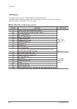
4-4-6 In
door
H
eat
Exch
a
ng
er
'
s
EVAP I
N
se
n
sor
dis
l
o
c
atio
n
error
×(O
peration)
◑
(T
imer)
◑
(F
an)
◑
(F
i
l
ter)
×(
Defrost)
t
I
ndoor
heat
e
x
changer
'
s
EVA
P
I
N
piping
sensor
has
been
dis
l
ocated
t
Refer
to
how
to
determine
be
l
ow
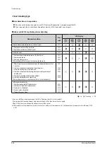
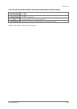
Indoor unit display
Criteria
Cause of problem
Outdoor unit display
x x x (x x x : T
he
address
of
the
error
occ
u
rred
indoor
u
nit)
1
.
H
ow
to
diagnose
1
)
D
u
ring
C
oo
l
ing
O
peration
2)
D
u
ring
H
eating
operation
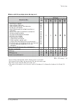
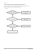
T
cond
,
o
u
t
- T
air
,
o
u
t
>
3
°C
OK
T
air
,
in
- T
e
v
a
,
o
u
t
> 4°C
N
O
T
air
,
in
- T
e
v
a
,
o
u
t
> 4°C
OK
C
ompressor
in
operation
&
I
ndoor
U
nit
operation
&
T
hermo
O
n
OK
E
rror
detai
l
s
B
reakawa
y E
rror
of
I
ndoor
H
eat
Ex
changer
EVA Ou
t
sensor
Av
erage
high
press
u
re
>
25kg
/
cm
²
OK
Av
erage
l
ow
press
u
re
> 8
.5kg
/
cm
²
OK
T
cond
,
o
u
t
- T
air
,
o
u
t
≥
3
°C
OK
T
air
,
in
- T
e
v
a
,
o
u
t
≥
2
°C
N
O
T
cond
,
o
u
t
- T
air
,
o
u
t
< -
2
°C
OK
C
ompressor
in
operation
& I
ndoor
U
nit
operation
& T
hermo
O
n
OK
E
rror
detai
l
s
B
reakawa
y E
rror
of
I
ndoor
H
eat
Ex
changer
EVA Ou
t
sensor
2.
H
ow
to
check
*
Hy
dro
U
nit
: B
efore
and
after
the
C
ompressor
operation
, EVA Ou
t
tempera
-
t
u
re
difference
is
l
ess
than
3
°C
.
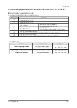
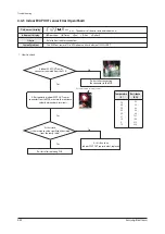
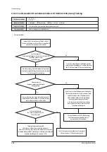
Restart operation after connecting
the connector to the PCB.
After separating the Indoor EVA In sensor
connector from the PCB, measure the
resistance value between the two terminals.
Yes
No
70
60
50
40
30
20
10
0
-10
2.2
3.0
4.2
5.8
8.3
12.1
18.0
27.3
43.0
Did the Indoor EVA In sensor
connector breakaway from the PCB?
Yes
No
Did the resistance value significantly
stray from the following temperature table?
Restart operation after replace the PCB.
Replace this part as it is the defective of the
Indoor EVA In sensor itself.
Temperature(
℃
) Resistance(K
Ω
)


