background image

EB 6493 EN 

 17-7

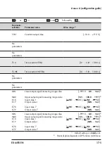
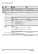
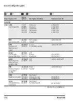
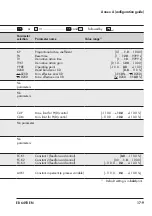
Annex A (configuration guide)


 

…   

 

……………   


or 


 

……………………………………   

 

………………… ……………………………


 or 


 

……………………   

 and 


, followed by   

Menu Function -CO-

Setting 

options

 1)

Description of functions

Parameter level -PA-

Parameter 

selection

Parameter name

Value range

 1)

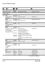
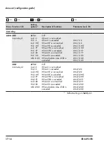
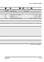
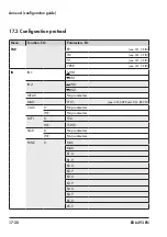
Set point

SETP

SP.VA

Internal set point W

on W

ON

SP.VA/W

W

 WINT

 WINT

 WRAN

 WRAN

Internal set point

Lower measuring range value W/W2

Upper measuring range value W/W2

Lower adjustment limit W/W2

Upper adjustment limit W/W2

[

 WRAN … 

0.0

 … 

 WRAN]

[–999 … 

0.0

 … 

 WINT]

[

 WINT … 

100.0

 … 9999]

[

 WINT … 

0.0

 … 

 WRAN]

[

 WRAN … 

100.0

 … 

 WINT]

 2)

Internal set point W2

oFF W2

on W2

OFF

ON

P.VA/W2

W2

Internal set point

[

 WRAN … 

0.0

 … 

 WRAN]

 2)

Input variable WE

oFF WE

on WE

F01 WE

OFF

External set point WE

Input for external feedback with 

three-step output

noPA SP.VA/WE

No 

parameters

F02 WE

Input for feedforward control

SP.FU

Set point ramp

oFF RAMP

OFF

F01 RAMP

Started with actual value by binary 

input BI1

SP.FU/RAMP

TSRW

Running time

[1 … 

10

 … 9999 s]

F02 RAMP Started with WIRA by binary input 

BI1

SP.FU/RAMP

WIRA

Initial value

[

 WINT … 

0.0

 … 

 WINT]

 2)

F03 RAMP

Without start conditions

Set point switchover

oFF CH.SP

F01 CH.SP

OFF

W(W2)/WE by binary input BI1

noPA SP.VA/CH.SP

No parameter

F02 CH.SP W/W2 by binary input BI1

1) 

Default setting is in 

bold

 print.

1) 

Default setting is in 

bold

 print.

2) 

Decimal place depends on DP function (AUX menu

Summary of Contents for Trovis 6493

Page 1: ...Translation of original instructions EB 6493 EN Firmware version 4 03 Edition August 2021 TROVIS 6493 Compact Controller...

Page 2: ...st you in mounting and operating the device safely The instructions are binding for handling SAMSON devices The images shown in these instructions are for illustration purposes only The actual product...

Page 3: ...pact controller 4 1 4 3 Transporting the compact controller 4 1 4 4 Storing the compact controller 4 1 5 Installation 5 1 5 1 Installation conditions 5 1 5 2 Preparation for installation 5 1 5 3 Mount...

Page 4: ...ss data I O 8 11 9 Operation 9 1 9 1 Setting the internal set point 9 1 9 2 Switchover between set points 9 1 9 3 Switching over to manual mode and changing the manipulated variable 9 3 9 4 AUX menu C...

Page 5: ...devices to SAMSON 14 1 15 Disposal 15 1 16 Certificates 16 1 17 Annex A configuration guide 17 1 17 1 Abbreviations 17 1 17 2 Configuration list 17 2 17 3 Configuration protocol 17 20 18 Annex B 18 1...

Page 6: ...Contents EB 6493 EN...

Page 7: ...forces or any other external factors Refer to the technical data for limits and fields of application as well as possible uses See the Design and principle of operation section Reasonably foreseeable...

Page 8: ...or by moving parts by taking appropriate precautions Plant operators and operat ing personnel must observe all hazard statements warning and caution notes in the refer enced documents Responsibilitie...

Page 9: ...KH 6493 These mounting and operating instructions EB 6493 describe the installation electrical wiring and operation of the controller In addition EB 6493 includes a list of all configuration set tings...

Page 10: ...of water Malfunction due to a configuration that does not meet the requirements of the appli cation The controller is configured for specific applications by setting configuration items and parameters...

Page 11: ...sered onto the nameplate on the side of the controller housing SAMSON TROVIS 6493 Made in Germany 1 6 5 2 3 4 7 8 9 10 1 Analog inputs IN1 and IN2 2 Binary input BI 3 Analog output Y 4 Binary outputs...

Page 12: ...s on the device 2 2 Article code TROVIS 6493 032 Compact Controller x Supply voltage 90 to 250 V AC 4 24 V AC DC 5 2 3 Firmware versions Firmware revisions Old New 4 01 4 02 Internal revisions 4 02 4...

Page 13: ...the analog output Y Analog inputs The analog inputs IN1 and IN2 can be ad justed to the following ranges 0 to 20 mA 4 to 20 mA 0 to 10 V 2 to 10 V Pt 100 Pt 1000 Ni 100 Ni 1000 resis tance thermometer...

Page 14: ...or Xd can be issued Binary outputs The binary outputs BO1 and BO2 are de signed as relays with double throw contacts They can either used as a three step output on off output or to monitor limit value...

Page 15: ...rameterize various SAMSON devices using device specific database modules The device module 6493 can be downloaded free of charge from our website at u www samsongroup com SERVICE SUPPORT Downloads TRO...

Page 16: ...ep ON OFF 3 step PWM TROVIS 6493 mA V Pt 100 Pt 1000 Ni 100 Ni 1000 Pot 1 k TROVIS VIEW Analog inputs Binary input Inter face Supply voltage Limit alarms Transistor output Fault alarm Supply output An...

Page 17: ...Zero 0 2 span 0 2 linearity 0 2 Effect of temperature 0 1 10 K for zero and span 1 Resolution 0 0024 mA 1 2 mV 0 012 with 0 to 20 mA 0 015 with 4 to 20 mA 0 012 with 0 to 10 V Transmitter supply Accor...

Page 18: ...20 mA load 740 0 2 to 10 V load 3 k Max permissible signal range 0 to 22 mA 0 to 11 V Error 0 2 Effect of temperature Zero 0 1 10 K span 0 1 10 K Resolution 0 0015 mA 0 0075 with 0 to 20 mA 0 0094 wi...

Page 19: ...nsport 20 to 70 C Mechanical environmental conditions af fecting storage transport and operation Sinusoidal vibration according to IEC 60068 2 6 2 to 9 Hz 3 5 mm amplitude 9 to 200 Hz 10 m s accelerat...

Page 20: ...3 8 EB 6493 EN Design and principle of operation 3 2 Dimensions 158 6 18 142 5 59 10 48 1 89 96 3 78 91 5 3 60 Fig 3 2 Dimensions in mm inch...

Page 21: ...5 215 61 219 15 222 68 Temperature C 340 350 360 370 380 390 400 410 420 430 440 Resistance 226 21 229 72 233 21 236 70 240 18 243 64 247 09 250 53 253 96 257 38 260 78 Temperature C 450 460 470 480 4...

Page 22: ...3 10 EB 6493 EN...

Page 23: ...ckaging in ac cordance with the local regulations 1x TROVIS 6493 Compact Controller including seal for panel mounting 0430 1495 1x Document IP 6493 Important Product Information 1x Accessory 1400 7411...

Page 24: ...x ternal influences e g impact Protect the compact controller against moisture and dirt In damp spaces pre vent condensation If necessary use a drying agent or heating Make sure that the ambient air i...

Page 25: ...make sure the following conditions are met The compact controller is not damaged Proceed as follows Lay out the necessary material and tools to have them ready during installation work 5 3 Mounting t...

Page 26: ...5 2 EB 6493 EN Installation 1 Mounting clamps 2 Panel 3 Seal 1 1 2 3 Panel cut out 45 0 6 x 92 0 8 Mounted depth including terminals 158 6 18 Dimensions in mm inch Fig 5 1 Installation...

Page 27: ...or outlet using the larg est possible cross section Connect the central grounding point and the PE grounding conductor with a cable with 10 mm wire cross section using the shortest route DANGER Induc...

Page 28: ...5 4 EB 6493 EN Installation Generally for potentiometers we recommend performing a zero and span calibration see CO ADJ Calibration of analog inputs and analog output in the Operation section Note...

Page 29: ...L L BO1 42 43 51 BO2 52 LIM 1 LIM 2 BO1 BO2 53 N 100 0 100 0 100 0 100 0 L L Analog input Supply output Analog input Analog output Binary input Binary output Supply voltage Binary output Binary output...

Page 30: ...5 6 EB 6493 EN...

Page 31: ...p output 5 Limit relay L1 active 6 Three step output 7 Fault alarm 8 Hand icon 9 After pressing W W2 Y or Xd is dis played with the value in 2 10 Bar reading of Xd in 11 Selector key 12 Selector key 1...

Page 32: ...the device sec tion Open parameter level Jump within the value range of an open parame ter Shift the decimal point one place to the right Manual automatic key Switch between manual and automatic mode...

Page 33: ...tive No reading 4 Three step output No reading 5 Limit relay L1 active No reading 6 Three step output or on off output No reading 7 Fault alarms u KH 6493 and the Malfunc tions section No reading 8 Ha...

Page 34: ...IS VIEW software is available in u EB 6661 An infrared interface is required for data transmission between the serial RS 232 port of the computer and the infrared interface on the controller A bracket...

Page 35: ...peration Xd W L2 1 L 0 7 m 25 Connector to RS 232 port Holding bracket Order no 1400 9769 Infrared adapter Order no 8864 0900 Fig 6 2 Connecting the infrared interface Fig 6 3 USB to RS 232 adapter or...

Page 36: ...6 6 EB 6493 EN...

Page 37: ...configuration level In the configuration menu the control ler is adapted to its control task by changing individual configuration items and parameters Annex A contains an overview of all possible sett...

Page 38: ...2 Enter menu 3 Select function parameter 4 Show setting 5 Activate editing mode for setting value 6 Change setting value 7 Confirm setting value 8 Open parameter level 1 After opening the configurati...

Page 39: ...KP 1 0 TN 120 TN IN CO IN1 4 20 mA 4 20 mA 0 10 V 0 0 IN1 0 0 IN1 100 0 IN1 100 0 IN1 PA IN1 1 1 1 1 1 2 4 6 7 8 3 5 6 7 3 5 6 7 3 5 1 2 Operating level Change control parameters Input IN1 Set input...

Page 40: ...ice Input IN2 Set input signal and measuring range Assign input variables CO CLAS In2 X In2 X In1 X In1 WE In1 WE In2 WE 3x 3x CO IN2 1000 PT 0 0 IN2 100 0 IN2 0 0 IN2 100 0 IN2 100 PT PA IN2 100 PT 1...

Page 41: ...et control re sponse Adjust the direction of action CO SP VA 0 0 W 0 0 W PA W on W SETP 1 CNTR CO C PID 5x CO DIRE dir d DI AC dir d DI AC in d DI AC 5x PI CP YP PI CP YP PId CP YP 120 TN 2x 2x 120 TN...

Page 42: ...e device OUT CO SAFE 6x CO Y VA 4 20 mA 0 10 V 6x 4 20 mA CO C OUT i Fb 3 STP 1 0 KPL1 60 TY PA C OUT oFF 2 3 S 3x 3x oFF 2 3 S 2x 2x 8x 8x 60 TY 1 1 1 Set three step output Analog output Set signal r...

Page 43: ...EB 6493 EN 7 7 Start up and configuration at the device AUX CO RE CO F02 MODE F01 MODE F02 MODE 1 TUNE I O ALRM Set restart con dition Fig 7 5 Schematic diagram of operation 5 5...

Page 44: ...TUNE or I O Enter menu Reading CO and abbreviated code of the first function in the current menu If you want to configure a different function Select the function you want to configure Open function...

Page 45: ...pressed Configuration and parameterization example The compact controller is to configured to be a PID controller The associated proportion al action coefficient KP is to be set to 1 5 Refer to the ov...

Page 46: ...ion time 1 10 9999 s TVK1 Derivative action gain 0 10 1 00 10 00 Y PRE Operating point 10 0 0 0 110 0 DZXD Dead band error Xd 0 0 110 0 DZXD Minimum effective error Xd 110 0 DZXD DZXD Maximum effectiv...

Page 47: ...ion of CNTR menu Open function Reading PI current setting of C PID function Activate editing mode for the function Reading Prompt for key number Only for operation with key number Enter valid key numb...

Page 48: ...the device 2x Change PI to PID control algorithm Confirm setting The editing mode is exited Change to the parameter level Reading PA and C PID CP YP blink in alternating sequence Open parameter level...

Page 49: ...mode for the parameter KP blinks Set proportional action coefficient KP to 1 5 Confirm setting The editing mode is exited If you want to change other parameters in the func tion select the parameters...

Page 50: ...upplied with the device This number allows configu ration settings and parameters to be changed regardless of user key number operation To avoid unauthorized use of the service key number we recommend...

Page 51: ...ey number If you enter an incorrect key number you are prompted again to enter the key number In this case 1 appears on the display instead of Activate deactivate operation with key number The control...

Page 52: ...ows configuration settings and pa rameters to be changed regardless of user key num ber operation To avoid unauthorized use of the ser vice key number we recommend removing the pag es German and Engli...

Page 53: ...device Enter your own key number 12 in this example To deactivate operation with key number select on the display Exit prompt for key number The controller returns to the configuration level Press un...

Page 54: ...ress to select W and use the cursor keys to set the value 5 In the operating level change the manipulated variable Y so that the controlled variable X has the same value as the set point W error Xd 0...

Page 55: ...point of the manipulated variable Y For a P controller every time the set point is changed the change of the operating point is also necessary if no steady state error is to exist 7 Switch to automat...

Page 56: ...t the value 6 Switch to automatic mode 7 In the PAR menu step up the KP parameter until the controlled variable shows an har monic oscillation pattern Every time the KP increases let the controlled sy...

Page 57: ...ting point of the manipulated variable 6 In the PAR menu set the Y PRE parameter to the previously determined operating point of the manipulated variable Y For a P controller every time the set point...

Page 58: ...step up the KP parameter until the controlled variable shows an har monic oscillation pattern Every time the KP increases let the controlled system oscillate e g by making small changes to the set poi...

Page 59: ...controller determines the control parameters from the course of the controlled variable After the adaptation is completed the controller issues the output value again which was active in manual mode...

Page 60: ...step change value Y JMP 7 In the TUNE menu select CO ADAP function Select run ADP S to start the adaptation How long the adaptation takes is determined by the time behavior of the controlled sys tem I...

Page 61: ...The controller can be configured using the TROVIS VIEW software 8 1 Communication 8 1 1 Interface Xd W L2 1 L 0 7 m 25 Connector to RS 232 port Holding bracket Order no 1400 9769 Infrared adapter Ord...

Page 62: ...ntrol Panel or assign a different COM port The driver can be downloaded from our website u www samsongroup com SERVICE SUPPORT Download TROVIS VIEW 3 Start TROVIS VIEW with device module TROVIS 6493 4...

Page 63: ...rom the Device menu The wizard for device addressing opens 2 Select Several devices of the same type are within reach The controllers within the reception range display their serial number 3 Enter the...

Page 64: ...to 9 These texts can be saved on the controller Edited texts are only displayed on the TROVIS VIEW software and printed on any associated documentation 8 2 2 Operation The Operation folder contains al...

Page 65: ...be deactivated during the switchover with TROVIS VIEW The infrared adapter must be connected to the computer and aligned to the infrared in terface of the compact controller see the Operation section...

Page 66: ...on troller The controller does not switch to automatic operation if the entire data record is trans ferred to the controller Internal error Internal error data point see the Malfunctions section 8 2 3...

Page 67: ...ing settings can be made Determining the type of input signal and the measuring range Signal monitoring Assigning analog inputs to the controlled variable X or external set point WE Units Filtering Ro...

Page 68: ...tself Example User defined unit for the controlled variable X 1 Double click Unit X to activate the data point 2 Select special from the drop down list 3 Click OK to confirm A new row Unit X special i...

Page 69: ...le 8 2 3 5 Output OUT The Output OUT folder corresponds to the OUT main group of the controller The control ler s output functions are set in this folder It is possible to determine whether the contro...

Page 70: ...Starting the adaptation 1 Open the Operation folder 2 Set manual mode Set Manual automatic switch to Manual and transfer the new setting to the controller 3 Determine the set point and transfer it to...

Page 71: ...O folder Differences between this folder and the I O main group of the controller In the I O main group under ADJ zero and span of the analog inputs and of the analog output can be calibrated This cal...

Page 72: ...8 12 EB 6493 EN...

Page 73: ...set point In this case press the selector key until the required variable is displayed The follow ing variables can be selected internal set point W manipulated variable Y error Xd and depending on t...

Page 74: ...active 4 Three step output 5 Limit relay L1 active 6 Three step output 7 Error message 8 Hand icon 9 After pressing W W2 Y or Xd is displayed with the value in 2 10 Bar reading of Xd in 11 Selector k...

Page 75: ...nt is shown Press key to read the manipulated variable Y 9 4 AUX menu CO ST IN Reset to default settings See Configuration Manual u KH 6493 The Reset to default settings function in the AUX menu cause...

Page 76: ...ged in extreme installation situations CO VIEW Top bottom viewing angle of display 01 VIEW Level 1 06 VIEW Level 6 10 VIEW Level 10 9 6 I O menu Process data You can read various variables and data in...

Page 77: ...this function I O CO BIN Binary values BI1 Binary input BI BO1 Binary output BO1 BO2 Binary output BO2 9 6 5 CO ADJ Calibration of analog inputs and analog output This functions allows you to calibrat...

Page 78: ...upper range value Alternating reading SPAN and IN1 IN2 9 Confirm upper range value Reading 100 0 and SPAN Calibrating analog outputs 1 Connect a high precision meter at the analog output Y 2 In the I...

Page 79: ...y output for error indication to be activated As soon as an error has been corrected it is no longer displayed The following list contains error messages possible causes and the recommended action We...

Page 80: ...PID setting impedes adaptation In CO C PID function select the cont rol algorithm P PI or PID and restart start up adaptation 35 ERR The control signal Y is smaller than 0 or greater than 100 during...

Page 81: ...d Remove obstacle or blocka ge and repeat the previous action The infrared adapter is not con nected to the computer Connect the infrared inter face to the computer and repeat the previous action Seri...

Page 82: ...the controller and it has been read out a temporary Error messages folder containing the incoming error messages is created in the Operation and Start up adaptation TUNE folders To clear the error mes...

Page 83: ...d testing Inspection and testing Action to be taken in the event of a negative result Check the markings labels and nameplates on the compact controller for their readability and completeness Immediat...

Page 84: ...11 2 EB 6493 EN...

Page 85: ...the local power suppliers Before connecting wiring performing any work on the compact controller or opening the controller disconnect the supply voltage and protect it against un intentional reconnect...

Page 86: ...12 2 EB 6493 EN...

Page 87: ...is only to be performed by personnel appropriately qualified to carry out such tasks 1 Remove infrared adapter and its bracket if mounted 2 Unscrew the threaded rods from the com pact controller 3 Rem...

Page 88: ...13 2 EB 6493 EN...

Page 89: ...or repair work 14 1 Returning devices to SAMSON Defective controllers can be returned to SAMSON for repair Proceed as follows to return devices to SAMSON 1 Put the compact controller out of opera tion...

Page 90: ...14 2 EB 6493 EN...

Page 91: ...as a producer of electrical and electronic equipment WEEE reg no DE 62194439 Observe local national and internation al refuse regulations Do not dispose of components lubricants and hazardous substanc...

Page 92: ...15 2 EB 6493 EN...

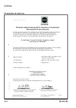
Page 93: ...included on the next pages EU declaration of conformity TR CU certificate The certificates shown were up to date at the time of publishing The latest certificates can be found on our website u www sam...

Page 94: ...mit den einschl gigen Harmonisierungsrechtsvorschriften der Union best tigt the conformity with the relevant Union harmonisation legislation is declared with est conforme la l gislation d harmonisatio...

Page 95: ...EB 6493 EN 16 3 Certificates TR CU certificate...

Page 96: ...16 4 EB 6493 EN Certificates...

Page 97: ...EB 6493 EN 16 5 Certificates...

Page 98: ...16 6 EB 6493 EN...

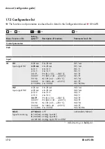
Page 99: ...escribed in detail in the Configuration Manual u KH 6493 17 1 Abbreviations X Controlled variable Y Manipulated variable W Internal set point W2 Internal set point WE External set point feedforward co...

Page 100: ...o 10 V Pt 100 100 500 C Pt 1000 100 500 C Ni 100 60 250 C Ni 1000 60 250 C 0 to 1000 IN1 mA IN1 mA IN1 V IN1 V IN1 PT IN1 PT IN1 NI IN1 PT IN1 KOHM IN2 Input signal IN2 0 20 mA 4 20 mA 0 10 V 2 10 V 1...

Page 101: ...ative action time Operating point 0 1 1 0 100 0 1 120 9999 s 1 10 9999 s 10 0 0 0 110 0 IN1 IN1 Lower measuring range value Upper measuring range value 999 0 0 0 IN1 IN1 100 0 9999 2 IN2 IN2 Lower mea...

Page 102: ...In2 X In1 X X IN2 X IN1 noPA CLAS X Assignment of WE to analog inputs In1 WE In2 WE WE IN1 WE IN2 noPA CLAS WE DI FI Filtering input variable X oFF X on X OFF ON DI FI X Filtering input variable WE o...

Page 103: ...999 0 0 0 MAX 2 MAX K1 X K1 Y K7 X K7 Y Upper output signal measuring range value Input value 1 Output value 1 Input value 7 Output value 7 MIN 100 0 9999 2 IN1 IN1 IN2 IN2 MIN MAX IN1 IN1 IN2 IN2 MI...

Page 104: ...External set point WE Input for external feedback with three step output noPA SP VA WE F02 WE Input for feedforward control SP FU Set point ramp oFF RAMP OFF F01 RAMP Started with actual value by bina...

Page 105: ...W W2 Upper measuring range value W W2 Lower adjustment limit W W2 Upper adjustment limit W W2 WRAN 0 0 WRAN 999 0 0 WINT WINT 100 0 9999 WINT 0 0 WRAN WRAN 100 0 WINT 2 W2 Internal set point WRAN 0 0...

Page 106: ...output F01 DP YP F02 DP YP To error To controlled variable noPA D PID DP YP CH CA Control mode selection P D PI D oFF CC P F01 CC P F02 CC P OFF By error By set point CH CA CC P CH CA CC P M ADJ Opera...

Page 107: ...error XD 0 1 1 0 100 0 1 120 9999 s 1 10 9999 s 0 10 1 00 10 00 10 0 0 0 110 0 0 0 110 110 DZXD DZXD 110 0 No parameters No parameters CLI P CLI M Max limit for PI D control Min limit for PI D contro...

Page 108: ...YP Ramp increasing start with 10 by BI1 RAMP RA YP F02 RA YP Ramp increasing decreasing start with Y1RA by BI1 F03 RA YP Limitation when manipulated variable decreases and increases F04 RA YP F05 RA...

Page 109: ...parameters Y Y Min manipulated variable Max manipulated variable 10 0 0 0 110 0 10 0 100 0 110 0 TSRA Y1RA Running time Initial value 1 9999 s 10 0 0 0 110 0 No parameter K1 X Input value 1 10 0 0 0...

Page 110: ...F C OUT 2 3 STP on 2 STP i Fb 3 STP On off output Three step output with internal feedback C OUT 2 STP C OUT 3 STP E Fb 3 STP Three step output with external feedback C OUT 3 STP PP 2 STP i PP 3 STP O...

Page 111: ...0 0 10 0 0 0 110 0 KPL1 KPL2 TYL1 Gain Y BO1 Gain Y BO2 Cycle duration Y BO1 0 1 1 0 100 0 0 1 1 0 100 0 1 0 10 0 9999 s TYL2 TYL1 Cycle duration Y BO2 Min duty cycle Y BO1 1 0 10 0 9999 s 0 1 1 0 s T...

Page 112: ...When XD is exceeded When absolute value of XD is exceeded LIM1 L1 X LIM1 L1 X LIM1 L1 WE LIM1 L1 WE LIM1 L1 YP LIM1 L1 YP LIM1 L1 XD LIM1 L1 XD LIM1 L1 XD LIM2 Limit relay L2 oFF L2 Lo L2 X Hi L2 X Lo...

Page 113: ...D LI HYS Limit for YPID Limit for XD Hysteresis Y 100 0 Y 110 0 0 0 110 0 0 10 0 50 100 0 LI X Limit for X IN1 100 0 IN1 2 3 IN2 100 0 IN2 2 3 LI WE Limit for WE IN1 100 0 IN1 2 3 IN2 100 0 IN2 2 3 LI...

Page 114: ...nctions parameters and code number noPA ST IN INIT FUnC INIT PArA INIT AdJ INIT All functions All parameters and code number Calibration values for IN1 IN2 Y KEYL Lock control keys oFF LOCK bi1 LOCK O...

Page 115: ...iguration guide or and followed by Parameter selection Parameter name Value range 1 Y1K1 Constant output value 10 0 0 0 110 0 No parameters No parameters No parameters No parameter No parameters 1 Def...

Page 116: ...analog inputs and outputs IN1 IN2 CO VA WE VA FE CO SP CO YPID YOUT Analog input IN1 Analog input IN2 Controlled variable before function generation WE before function generation WE after function gen...

Page 117: ...d by Parameter selection Parameter name Value range 1 KP TN TV Y JMP Proportional action coefficient Reset time Derivative action time Step change value for adaptation 0 1 1 0 100 0 1 120 9999 s 1 10...

Page 118: ...KP see CO C PID TN see CO C PID TV see CO C PID Y PRE see CO C PID IN IN1 IN1 IN1 IN2 IN2 IN2 MEAS No parameters MAN Y1K1 see CO SAFE and CO RE CO CLAS X No parameters WE No parameters DI FI X TS X WE...

Page 119: ...e Menu Function CO Parameters PA IN FUNC X K6 X K6 Y K7 X K7 Y WE MIN MAX K1 X K1 Y K2 X K2 Y K3 X K3 Y K4 X K4 Y K5 X K5 Y K6 X K6 Y K7 X K7 Y SETP SP VA W W WINT WINT WRAN WRAN W2 W2 WE No parameter...

Page 120: ...R TV see PAR TVK1 TV see PAR DZXD DZXD DZXD SIGN No parameters D PID No parameters CH CA CLI P CLI M M ADJ No parameters DIRE No parameters F FOR FC K1 FC K2 FC K3 AC VA AV K1 OUT SAFE Y1K1 see CO MAN...

Page 121: ...arameters PA OUT FUNC K3 Y K4 X K4 Y K5 X K5 Y K6 X K6 Y K7 X K7 Y Y VA No parameters Y SRC No parameters CALC CA K1 CA K2 CA K3 C OUT KPL1 KPL2 TYL1 TYL2 TYL1 TYL2 XSDY TZ TY B OUT B OUT1 No paramete...

Page 122: ...on guide Menu Function CO Parameters PA ALRM LIM2 LI X LI WE LI YP LI XD LI HYS AUX RE CO Y1K1 see CO MAN and CO SAFE ST IN No parameters KEYL No parameters VIEW No parameters FREQ No parameters DP No...

Page 123: ...re for infrared adapter Order no 1400 9769 USB to RS 232 adapter Order no 8812 2001 Driver for USB to RS 232 adapter u www samsongroup com Service Support Download TROVIS VIEW USB RS 232 adapter 8812...

Page 124: ...u can reach our after sales service at aftersalesservice samsongroup com Addresses of SAMSON AG and its subsid iaries The addresses of SAMSON its subsidiaries representatives and service facilities wo...

Page 125: ......

Page 126: ......

Page 127: ......

Page 128: ...2021 11 03 English SAMSON AKTIENGESELLSCHAFT Weism llerstra e 3 60314 Frankfurt am Main Germany Phone 49 69 4009 0 Fax 49 69 4009 1507 samson samsongroup com www samsongroup com EB 6493 EN...

Reviews: