background image

14-18  

EB 8355-2 EN

Summary of Contents for 3767

Page 1: ...Translation of original instructions EB 8355 2 EN Type 3767 Electropneumatic Positioner Edition February 2022...

Page 2: ...estions about these instructions contact SAMSON s After sales Service aftersalesservice samsongroup com The mounting and operating instructions for the devices are included in the scope of delivery Th...

Page 3: ...4 Storing the positioner 4 1 5 Installation 5 1 5 1 Installation conditions 5 1 5 2 Preparation for installation 5 1 5 2 1 Determining the operating direction of the positioner control loop 5 2 5 3 P...

Page 4: ...tropneumatic to pneumatic 9 2 9 3 Installing the limit switches 9 3 9 4 Installing the solenoid valve 9 3 9 5 Removing the solenoid valve 9 4 9 6 Periodic inspection and testing of the positioner 9 4...

Page 5: ...for the following applications Use outside the limits defined during sizing and by the technical data Furthermore the following activities do not comply with the intended use Use of non original spare...

Page 6: ...f inadmissible motions or forces are produced in the pneumatic actuator as a result of the supply pressure it must be restricted using a suitable supply pressure reducing station Responsibilities of t...

Page 7: ...of the atmosphere and ultimately to death Observe EN 60079 14 VDE 0165 Part 1 for work on the positioner in hazard ous areas Work in hazardous areas must only be performed by personnel who has under g...

Page 8: ...amination certificates when interconnecting intrinsically safe electrical equipment Ui or U0 li or I0 Pi or P0 Ci or C0 and Li or L0 1 3 Notes on possible property damage NOTICE An incorrect electric...

Page 9: ...wing for servicing equipment in a section relevant for explosion pro tection The equipment must not be put back into operation until a qualified inspector has assessed the equipment according to explo...

Page 10: ...1 6 EB 8355 2 EN...

Page 11: ...circuits i p Positioner single acting Input Made in Germany SAMSON AG D 60314 Frankfurt Date 3767 Limit switches inductive Ui Var ID Model Serial no Solenoid valve Supply Ii Pi Ci Li Ui Ii Pi Ci Li U...

Page 12: ...C D E F G Class I Div 2 Groups A B C D Class II Div 2 Groups F G Class III 3 IECEx Ex ia I IIC T6 IP 65 Ex nI IIC T6 IP 65 6 ATEX II 3G Ex nA II T6 8 Additional equipment Without 0 Inductive limit swi...

Page 13: ...int 4 to 20 mA 1 0 to 20 mA 2 1 to 5 mA 3 Temperature range Standard 0 Low temperature version Tmin 50 C optional limit switches solenoid valve 2 1 2 Special versions Without 0 0 0 1 No longer availab...

Page 14: ...2 4 EB 8355 2 EN...

Page 15: ...of the positioner The supply air is supplied to the booster 10 and the pressure regulator 9 The controlled supply air flows through the Xp restriction 8 and the nozzle 2 1 2 2 and hits the diaphragm l...

Page 16: ...signal of 4 to 20 mA The tuning of the position transmitter ensures that both end positions valve CLOSED or valve OPEN as well as all intermediate po sitions can be signalized Since the valve po sitio...

Page 17: ...B 8355 2 EN 3 3 Design and principle of operation Travel 7 8 9 10 11 12 6 1 4 6 2 2 1 3 2 2 5 1 1 1 1 2 Pe 9 Supply V Pst Q Xp p i mA 13 4 6 1 6 2 3 7 8 9 11 Fig 3 1 Functional diagram and inside view...

Page 18: ...2 5 proportional action coefficient Kp 100 to 40 Air consumption At 1 4 bar supply pressure 280 ln h At 6 bar supply pressure 280 ln h With lowest setting of pressure regulator Air output capacity Act...

Page 19: ...bar 0 5 s 1 s 1 5 s 4 s 0 4 to 2 bar 2 s 2 5 s 8 s 0 6 to 3 bar 1 s 1 5 s 5 s Position transmitter 1 2 Output circuit intrinsically safe Output signal Two wire connection 4 to 20 mA reversible operati...

Page 20: ...Valid until 2025 03 18 3767 3 CSA Number 1607848 Ex ia IIC T6 Class I Zone 0 Class I II Div 1 Groups A B C D E F D Class I II Div 2 Groups A B C D E F D Date 2005 09 16 FM Number 3020228 Class I Zone...

Page 21: ...imensional drawings 28 14 29 150 164 19 5 37 68 185 76 Supply 9 Output 36 Direct attachment to the Type 3277 Actuator Attachment according to IEC 60534 and NAMUR 36 N1 113 N2 200 58 56 68 185 29 164 7...

Page 22: ...peration Dimensional drawings Attachment to rotary actuators with pneumatic reversing amplifier 44 19 5 39 35 68 185 164 29 50 46 76 50 150 82 56 66 28 5 28 5 Output 1 A1 Output 2 A2 Supply Z Fulcrum...

Page 23: ...sequence Do not remove the packaging and the protective caps on the pneumatic ports until immediately before installation Dispose and recycle the packaging in ac cordance with the local regulations 4...

Page 24: ...sture and dirt In damp spaces prevent con densation If necessary use a drying agent or heating Make sure that the ambient air is free of acids or other corrosive media Observe storage temperature depe...

Page 25: ...of the actu ator and plug stem by inserting objects into the yoke Risk of malfunction due to incorrect mount ing parts accessories Only use the mounting parts and acces sories listed in these mountin...

Page 26: ...tion of the turn board the adjusted operating direction and the associated symbol is visible If the re quired operating direction does not corre spond to the visible symbol or if the operat ing direct...

Page 27: ...ket 16 Cover Switchover plate Signal pressure input Signal pressure input for left attachment Seal with filter With right attachment Marking Marking Symbol Actuator stem extends Actuator stem retracts...

Page 28: ...e areas 7 Make sure that the tip of the gasket 16 projecting from the side of the connec tion block Fig 5 1 middle is positioned to match the actuator symbol for the ac tuator s fail safe action actua...

Page 29: ...EB 8355 2 EN 5 5 Installation Travel 7 8 9 10 11 12 6 1 4 6 2 2 1 3 2 2 5 1 1 1 1 2 Pe 9 Supply V Pst Q Xp p i mA 13 4 6 1 6 2 3 7 8 9 11 Fig 5 3 Functional diagram and inside view...

Page 30: ...at the back of positioner In this case the signal pressure must be transmitted from the signal pressure output to the actuator over an addi tional connecting plate Table 5 5 The swi tchover plate is n...

Page 31: ...tem retracts FE fail safe action Operating direction Operating direction Operating direction Operating direction 20 Output and supply Output and supply Input Fig 5 5 Attachment to the left or right of...

Page 32: ...ight valve rod Fig 5 5 and screw tight using the nut 14 Make sure that the adapter housing is at the correct height to mount the lever 1 so that it is in a horizontal position when the valve is at mid...

Page 33: ...10a Attachment to NAMUR rib Attachment to rods 1 Lever N1 N2 2 Pin 3 Plate 4 Clip 5 Clamping plate 6 Screw 7 Pointer 8 Shaft 9 Lever of positioner 10a Coupling pin 10b Lock nut 11 Bracket 12 Studs 13...

Page 34: ...using a reversing amplifier the pres sure regulator 9 Fig 5 3 must be turned clockwise as far as it will go see sec tion 5 4 2 When attaching the positioner to the SAMSON Type 3278 Rotary Actuator Fi...

Page 35: ...VDE 3845 09 2010 Attachment SAMSON Type 3278 1 Positioner 2 Intermediate piece 3 Lever with feeler roll 4 Adapter 5 Transmission lever 6 Screws 7 Dial plate 8 Cam disk 9 Washer 10 Mounting bracket 11...

Page 36: ...ontrol valve assembly with a rotary actuator with spring return mechanism that opens counterclockwise The arrangement of the springs in the actuator determines the fail safe position of the valve Fig...

Page 37: ...reasing Set point Signal pressure Valve Characteristic Set point Signal pressure Valve Characteristic increases increases opens N decreases increases opens I 90 6 0 30 0 90 6 0 30 0 Feeler roll Starti...

Page 38: ...Charac teristic decreases A1 increases A2 decreases opens I 90 6 0 30 0 90 6 0 30 0 Feeler roll Starting point N Starting point I Hole to secure the cam disk Insert clip and press the flaps outwards V...

Page 39: ...e s direction of ro tation Securing the aligned cam disk To prevent the cam disk from turning drill a hole into the adapter 4 or coupling 11 to allow a 2 mm dowel pin to be inserted Select one of the...

Page 40: ...ctuator that causes the valve to close when the pressure rises Pressure gauge attachment The mounting sequence shown in Fig 5 10 remains unchanged Screw a pressure gauge bracket onto the connections A...

Page 41: ...1 1 5 1 6 Z A2 1 4 A1 A2 Output 38 Supply 9 1 3 1 2 1 1 1 6 Z A1 From the positioner Control signals to the actuator 1 Reversing amplifier 1 1 Special screws 1 2 Gasket 1 3 Special nuts 1 4 Rubber sea...

Page 42: ...e action actua tor stem extends or actuator stem retracts Exhaust air Models with index 3767 x x 03 and higher are equipped with a hinged cover without its own exhaust air port The exhaust air con nec...

Page 43: ...using a pressure gauge accessories 5 5 Adjusting the positioner Intrinsic safety rendered ineffective in in trinsically safe devices Only connect intrinsically safe devices in tended for use in intrin...

Page 44: ...ter 6 2 the span i e the upper range value is adjusted at the span adjuster 6 1 When the positioner is controlled by a computer whose signal is limited e g between 4 to 20 mA set the positioner to the...

Page 45: ...range from 4 5 to 20 mA This is the only way to ensure that the actuator is completely vented and the valve com pletely closed when the controller issues a 4 mA signal For operating direction set the...

Page 46: ...int 20 mA Operating direction Lower range val ue of set point 4 mA The required signal pressure is either indicat ed on the positioner label or it can be rough ly calculated as described in section 5...

Page 47: ...g 2 is located in the inductive field of the switch the switch assumes a high resistance When it moves outside the field the switch assumes a low resistance The limit switches are usually adjusted to...

Page 48: ...ted by the LED on the switching amplifier To guarantee the switching under all am bient conditions adjust the switching point approx 2 before the mechanical stop OPEN CLOSED Note Table 5 2 Assignment...

Page 49: ...tches 3 and 4 to roughly set the span i e the upper range value and the SPAN potentiometer for fine tuning The ad justed value is always based on a 20 mA signal Example Move the valve to the open posi...

Page 50: ...SPAN potentiometer 4 Turn the SPAN potentiometer until the ammeter shows exactly 20 mA Since the zero point and span have a mutual influence on each other repeat the correction procedure at both pote...

Page 51: ...li or I0 Pi or P0 Ci or C0 and Li or L0 Selecting cables and wires Observe clause 12 of EN 60079 14 2008 VDE 0165 Part 1 for installation of the in trinsically safe circuits Clause 12 2 2 7 applies w...

Page 52: ...er mit the connection of additional equipment The position transmitter is operated on a two wire circuit The usual supply voltage is 24 V DC Taking the resistance of the supply leads into account the...

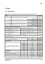
Page 53: ...e g a solenoid valve Type 3277 5xxxxxx 00 Actuator old G 1 8 Type 3277 5xxxxxx 00 Actuator old 1 8 NPT 1400 6820 1400 6821 New connecting plate Type 3277 5xxxxxx 01 Actuator new or higher G 1 8 and 1...

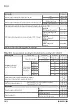
Page 54: ...9895 Table 5 6 Accessories and mounting kits for attachment according to IEC 60534 6 Mounting kits Control valve Travel mm With lever Order no NAMUR mounting kit see Fig 5 6 for parts Valve with cast...

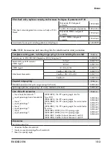
Page 55: ...00 7118 Camflex I DN 125 to 250 1400 7119 Camflex II 1400 7120 Required range spring Order no Standard operation of set point range spring 2 4 5 coils 1400 6443 Split range operation range spring 1 9...

Page 56: ...0 6782 Nickel plated brass 1400 6979 Adapter PG 13 5 to NPT Version Order no Metal 1400 7109 Painted blue 1400 7110 Device index 3767 x x and higher 04 M20x1 5 cable gland Version Clamping range Order...

Page 57: ...zard arising from moving parts on the valve Do not touch any moving valve parts while the control valve is in operation Before performing any mounting or in stallation work on the positioner put the c...

Page 58: ...6 2 EB 8355 2 EN...

Page 59: ...hazard arising from moving parts on the valve Do not touch any moving valve parts while the control valve is in operation Before performing any mounting or in stallation work on the positioner put th...

Page 60: ...7 2 EB 8355 2 EN...

Page 61: ...tallation work on the positioner put the control valve out of operation by discon necting and locking the supply air and control signal Do not impede the movement of the actu ator and plug stem by ins...

Page 62: ...r Check the seals in the connecting plate The set point span is not reached at a 100 sig nal Check whether the correct range spring has been selected Check the adjusted air output and proportional ban...

Page 63: ...e maximum permissible electric values specified in the EC type examination certificates when intercon necting intrinsically safe electrical equip ment Ui or U0 li or I0 Pi or P0 Ci or C0 and Li or L0...

Page 64: ...he cam disk and turn the turn board 9 2 Converting a positioner from electropneumatic to pneumatic The electropneumatic positioner can be con verted into a Type 3766 Pneumatic Position er with the fol...

Page 65: ...e the connecting cable to the termi nals and fasten brown blue 5 Refasten the bracket with plate 1 and stick the adhesive label for the limit switches on the housing cover 6 Screw additional cable gla...

Page 66: ...olenoid valve from terminals 81 82 2 Unscrew the two screws 7 that are not sealed with paint and remove the sole noid valve with its connecting cable 3 Place the rubber gasket on the spigot of the cov...

Page 67: ...2 EN 9 5 Servicing 1 2 2 3 4 5 6 7 8 9 1 Label 2 Screw 3 Cover with rubber seal 4 Terminal block 5 Plate 6 Solenoid valve 7 Screw 8 Seals 9 Metal plate Fig 9 2 Installing the limit switches and soleno...

Page 68: ...Clean any inscriptions that are covered with dirt and are illegible Check the positioner and leakage sensor if installed to ensure they are mounted firmly Tighten the any loose mounting screws Check...

Page 69: ...has under gone special training or instructions or who is authorized to work on explo sion protected devices in hazardous ar eas The process is disturbed by interrupting closed loop control Do not mo...

Page 70: ...10 2 EB 8355 2 EN...

Page 71: ...dous areas Work in hazardous areas must only be performed by personnel who has under gone special training or instructions or who is authorized to work on explo sion protected devices in hazardous ar...

Page 72: ...11 2 EB 8355 2 EN...

Page 73: ...ment the passing of the routine test by attaching a mark of conformi ty to the device Replace explosion protected components on ly with original routine tested components by the manufacturer Devices t...

Page 74: ...12 2 EB 8355 2 EN...

Page 75: ...as a producer of electrical and electronic equipment WEEE reg no DE 62194439 Observe local national and internation al refuse regulations Do not dispose of components lubricants and hazardous substan...

Page 76: ...13 2 EB 8355 2 EN...

Page 77: ...next pages EU declaration of conformity for Type 3767 EU declaration of conformity for Type 3767 1 EU declaration of conformity for Type 3767 8 EAC certificate for Type 3767 ATEX EC type examination c...

Page 78: ...14 2 EB 8355 2 EN...

Page 79: ...EB 8355 2 EN 14 3...

Page 80: ...14 4 EB 8355 2 EN...

Page 81: ...EB 8355 2 EN 14 5...

Page 82: ...DUH LQYDOLG 7KLV 6WDWHPHQW RI RQIRUPLW PD EH UHSURGXFHG RQO LQ LWV HQWLUHW ZLWKRXW DQ FKDQJHV WUDFWV RU FKDQJHV VKDOO UHTXLUH WKH SULRU DSSURYDO RI WKH 3K VLNDOLVFK 7HFKQLVFKH XQGHVDQVWDOW 3K VLNDOLV...

Page 83: ...O DUH LQYDOLG 7KLV 6WDWHPHQW RI RQIRUPLW PD EH UHSURGXFHG RQO LQ LWV HQWLUHW ZLWKRXW DQ FKDQJHV WUDFWV RU FKDQJHV VKDOO UHTXLUH WKH SULRU DSSURYDO RI WKH 3K VLNDOLVFK 7HFKQLVFKH XQGHVDQVWDOW 3K VLNDOL...

Page 84: ...G 7KLV 6WDWHPHQW RI RQIRUPLW PD EH UHSURGXFHG RQO LQ LWV HQWLUHW ZLWKRXW DQ FKDQJHV WUDFWV RU FKDQJHV VKDOO UHTXLUH WKH SULRU DSSURYDO RI WKH 3K VLNDOLVFK 7HFKQLVFKH XQGHVDQVWDOW 3K VLNDOLVFK 7HFKQLVF...

Page 85: ...OLG 7KLV 6WDWHPHQW RI RQIRUPLW PD EH UHSURGXFHG RQO LQ LWV HQWLUHW ZLWKRXW DQ FKDQJHV WUDFWV RU FKDQJHV VKDOO UHTXLUH WKH SULRU DSSURYDO RI WKH 3K VLNDOLVFK 7HFKQLVFKH XQGHVDQVWDOW 3K VLNDOLVFK 7HFKQL...

Page 86: ...KLV 6WDWHPHQW RI RQIRUPLW PD EH UHSURGXFHG RQO LQ LWV HQWLUHW ZLWKRXW DQ FKDQJHV WUDFWV RU FKDQJHV VKDOO UHTXLUH WKH SULRU DSSURYDO RI WKH 3K VLNDOLVFK 7HFKQLVFKH XQGHVDQVWDOW 3K VLNDOLVFK 7HFKQLVFKH...

Page 87: ...DO DUH LQYDOLG 7KLV 6WDWHPHQW RI RQIRUPLW PD EH UHSURGXFHG RQO LQ LWV HQWLUHW ZLWKRXW DQ FKDQJHV WUDFWV RU FKDQJHV VKDOO UHTXLUH WKH SULRU DSSURYDO RI WKH 3K VLNDOLVFK 7HFKQLVFKH XQGHVDQVWDOW 3K VLNDO...

Page 88: ...14 12 EB 8355 2 EN...

Page 89: ...EB 8355 2 EN 14 13...

Page 90: ...14 14 EB 8355 2 EN...

Page 91: ...EB 8355 2 EN 14 15...

Page 92: ...14 16 EB 8355 2 EN...

Page 93: ...EB 8355 2 EN 14 17...

Page 94: ...14 18 EB 8355 2 EN...

Page 95: ...EB 8355 2 EN 14 19...

Page 96: ...14 20 EB 8355 2 EN...

Page 97: ...EB 8355 2 EN 14 21...

Page 98: ...14 22 EB 8355 2 EN...

Page 99: ...EB 8355 2 EN 14 23...

Page 100: ...14 24 EB 8355 2 EN...

Page 101: ...EB 8355 2 EN 14 25...

Page 102: ...14 26 EB 8355 2 EN...

Page 103: ...EB 8355 2 EN 14 27...

Page 104: ...14 28 EB 8355 2 EN...

Page 105: ...a solenoid valve Type 3277 5xxxxxx 00 Actuator old G 1 8 Type 3277 5xxxxxx 00 Actuator old 1 8 NPT 1400 6820 1400 6821 New connecting plate Type 3277 5xxxxxx 01 Actuator new or higher G 1 8 and 1 8 NP...

Page 106: ...0 9895 Table 15 2 Accessories and mounting kits for attachment according to IEC 60534 6 Mounting kits Control valve Travel mm With lever Order no NAMUR mounting kit see Fig 5 6 for parts Valve with ca...

Page 107: ...118 Camflex I DN 125 to 250 1400 7119 Camflex II 1400 7120 Required range spring Order no Standard operation of set point range spring 2 4 5 coils 1400 6443 Split range operation range spring 1 9 5 co...

Page 108: ...mm 1400 6986 Nickel plated brass 6 to 12 mm 1890 4875 M20x1 5 to NPT adapter Version Order no Powder coated aluminum 0310 2149 15 2 After sales service Contact our after sales service for support con...

Page 109: ......

Page 110: ...2 EB 8355 2 EN...

Page 111: ...EB 8355 2 EN 3...

Page 112: ...2022 05 12 English SAMSON AKTIENGESELLSCHAFT Weism llerstra e 3 60314 Frankfurt am Main Germany Phone 49 69 4009 0 Fax 49 69 4009 1507 samson samsongroup com www samsongroup com EB 8355 2 EN...

Reviews: