5-26
EB 8355-2 EN
Installation
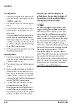
Zero adjustment
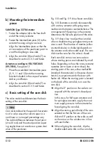
1. Use the input signal of the positioner to
move the valve to closed position (valve
CLOSED, travel 0 %).
2. The ammeter must now indicate approx.
4 mA.
3. Correct smaller deviations at the ZERO
potentiometer until the meter shows ex-
actly 4 mA.
For larger deviations that cannot be cor-
rected using the potentiometer (adjust-
ment range of approx. 20 turns), set the
switches 1 and 2 to indicate an mA val-
ue which is within the adjustment range
of the ZERO potentiometer.
4.
Set the zero point to exactly 4 mA using
the ZERO potentiometer.
Span adjustment
1. Use the input signal of the positioner to
move the valve to closed position (valve
CLOSED, travel 100 %).
2. The ammeter must now indicate approx.
20 mA.
3. Correct smaller deviations at the SPAN
potentiometer until the meter shows ex-
actly 20 mA. If deviations are too high,
set the switches 3 and 4 to indicate an
mA signal which is within the adjustment
range of the SPAN potentiometer.
4. Turn the SPAN potentiometer until the
ammeter shows exactly 20 mA.
Since the zero point and span have a
mutual influence on each other, repeat
the correction procedure at both potenti-
ometers until both values are correct.
Every time you make a change as de
-
scribed above, the zero point and span of
the positioner must be readjusted before
adjusting the position transmitter.
The following applies to positioners with
adapter housing for NAMUR attachment:
When the positioner and the position trans-
mitter signal have different operating direc-
tions (<< and <>), it may be impossible to
adjust the zero point of the transmitter signal
due to the additional deflection caused by
the bracket (28) of the adapter housing.
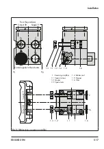
In this case, readjust the black pointer so that
the sensor of the position transmitter reaches
the control range (see section 5.3.2
Unscrew the clamp. For “actuator stem ex-
tends” (FA), shift the pointer upward towards
the actuator; for "actuator stem retracts"
(FE), shift the pointer downward towards the
valve. For valves with rod-type yoke, slightly
shift the positioner on the rod in the down-
ward (FE) or upward (FA) direction.
Note
Summary of Contents for 3767
Page 10: ...1 6 EB 8355 2 EN...
Page 14: ...2 4 EB 8355 2 EN...
Page 58: ...6 2 EB 8355 2 EN...
Page 60: ...7 2 EB 8355 2 EN...
Page 70: ...10 2 EB 8355 2 EN...
Page 72: ...11 2 EB 8355 2 EN...
Page 74: ...12 2 EB 8355 2 EN...
Page 76: ...13 2 EB 8355 2 EN...
Page 78: ...14 2 EB 8355 2 EN...
Page 79: ...EB 8355 2 EN 14 3...
Page 80: ...14 4 EB 8355 2 EN...
Page 81: ...EB 8355 2 EN 14 5...
Page 88: ...14 12 EB 8355 2 EN...
Page 89: ...EB 8355 2 EN 14 13...
Page 90: ...14 14 EB 8355 2 EN...
Page 91: ...EB 8355 2 EN 14 15...
Page 92: ...14 16 EB 8355 2 EN...
Page 93: ...EB 8355 2 EN 14 17...
Page 94: ...14 18 EB 8355 2 EN...
Page 95: ...EB 8355 2 EN 14 19...
Page 96: ...14 20 EB 8355 2 EN...
Page 97: ...EB 8355 2 EN 14 21...
Page 98: ...14 22 EB 8355 2 EN...
Page 99: ...EB 8355 2 EN 14 23...
Page 100: ...14 24 EB 8355 2 EN...
Page 101: ...EB 8355 2 EN 14 25...
Page 102: ...14 26 EB 8355 2 EN...
Page 103: ...EB 8355 2 EN 14 27...
Page 104: ...14 28 EB 8355 2 EN...
Page 109: ......
Page 110: ...2 EB 8355 2 EN...
Page 111: ...EB 8355 2 EN 3...

