5-12
EB 8355-2 EN
Installation
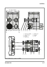
b) Mounting the intermediate
piece
SAMSON Type 3278 Actuator
1. Fasten the adapter (4) to the free shaft
end of the rotary actuator.
2. Fasten the intermediate piece (2) to the
actuator housing using two screws.
Align the intermediate piece so that the
air connections of the positioner point to-
ward the diaphragm case side.
3.
Align the cam disk (8) and scale (7) as
described in section 5.3.3 and fasten.
Actuators according to VDI/VDE 3845
(09/2010),
fixing level 2
1. Place the assembled intermediate piece
(2, 9, 11 and 12) onto the mounting
bracket included in the scope of actuator
delivery and fasten.
2.
Align the cam disk (8) and scale (7) as
described in section 5.3.3 and fasten.
c) Basic setting of the cam disk
The valve model used determines the basic
setting of the cam disk.
Cam disks tailored to the special characteris-
tic of a valve cause the valve to open in a
non-linear or non-equal percentage way.
The visible difference between the set point
(4 to 20 mA) and the actual position (open
-
ing angle) does not constitute a system devi
-
ation of the positioner.
and
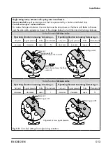
show linear cam disks.
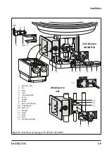
illustrates a control valve assembly
with a rotary actuator with spring-return
mechanism that opens counterclockwise. The
arrangement of the springs in the actuator
determines the fail-safe position of the valve.
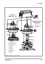
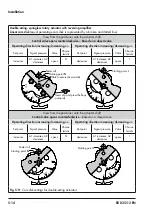
shows how to adjust the cam disk
when a double-acting springless rotary actu-
ator is used. The direction of rotation (either
counterclockwise or clockwise) depends on
the actuator and valve model used. The cam
disk must be set when the valve is closed.
Each cam disk carries two cam sections
whose starting points are indicated by small
holes. Depending on how the rotary actuator
operates (air-to-open or air-to-close), the
starting point of the cam, either marked
N
(standard characteristic) or
I
(reverse charac-
teristic), must point towards the lever with
feeler roll. When the starting point is located
on the back of the cam disk, turn over the
cam disk.
Î
Align the 0° position on the scale to cor
-
respond with the actuator's closed posi-
tion.
In this case, for fail-open actuators and
for springless actuators, apply the maxi-
mum supply pressure to the actuator be-
fore aligning the cam disk.
Î
Align the starting point (hole) of the cam
selected so that the fulcrum of the cam
disk and 0° position on the scale as well
as the arrow on the window are in line
with each other.
Î
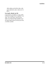
When aligning the cam disk, clip the
double-sided scale disk on the cam disk,
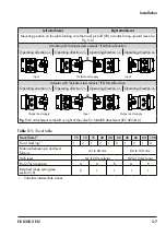
Single-acting rotary actuator with spring-return mechanism
Linear cam disk
(equal percentage cam disk is represented by a broken and dotted line)
Control valve opens counterclockwise
For valves that open clockwise, the cam disk must be turned over so that lever with feeler roll moves
over the same disk segments as shown in the images below, but with the cam disk turning clockwise.
Fail-safe action:
fail-close valve
Operating direction increasing/increasing >>
Operating direction increasing/decreasing <>
Set point
Signal pressure
Valve
Characteristic
Set point
Signal pressure
Valve
Characteristic
increases
increases
opens
N
decreases
increases
opens
I
90˚
60˚
30˚
0˚
90˚
60˚
30˚
0˚
Feeler roll
Starting point
N
Starting point
I
Hole to secure the cam disk
Insert clip and press the flaps
outwards
Fail-safe action:
fail-open valve
Operating direction increasing/increasing >>
Operating direction increasing/decreasing <>
Set point
Signal pressure
Valve
Characteristic
Set point
Signal pressure
Valve
Characteristic
decreases
decreases
opens
I
increases
decreases
opens
N
90˚
60˚
30˚
0˚
90˚
60˚
30˚
0˚
Feeler roll
Starting point
N
Starting point
I
Alignment at max. signal pressure
Fig. 5-8:
Cam disk settings for single-acting actuators
Note
Summary of Contents for 3767
Page 10: ...1 6 EB 8355 2 EN...
Page 14: ...2 4 EB 8355 2 EN...
Page 58: ...6 2 EB 8355 2 EN...
Page 60: ...7 2 EB 8355 2 EN...
Page 70: ...10 2 EB 8355 2 EN...
Page 72: ...11 2 EB 8355 2 EN...
Page 74: ...12 2 EB 8355 2 EN...
Page 76: ...13 2 EB 8355 2 EN...
Page 78: ...14 2 EB 8355 2 EN...
Page 79: ...EB 8355 2 EN 14 3...
Page 80: ...14 4 EB 8355 2 EN...
Page 81: ...EB 8355 2 EN 14 5...
Page 88: ...14 12 EB 8355 2 EN...
Page 89: ...EB 8355 2 EN 14 13...
Page 90: ...14 14 EB 8355 2 EN...
Page 91: ...EB 8355 2 EN 14 15...
Page 92: ...14 16 EB 8355 2 EN...
Page 93: ...EB 8355 2 EN 14 17...
Page 94: ...14 18 EB 8355 2 EN...
Page 95: ...EB 8355 2 EN 14 19...
Page 96: ...14 20 EB 8355 2 EN...
Page 97: ...EB 8355 2 EN 14 21...
Page 98: ...14 22 EB 8355 2 EN...
Page 99: ...EB 8355 2 EN 14 23...
Page 100: ...14 24 EB 8355 2 EN...
Page 101: ...EB 8355 2 EN 14 25...
Page 102: ...14 26 EB 8355 2 EN...
Page 103: ...EB 8355 2 EN 14 27...
Page 104: ...14 28 EB 8355 2 EN...
Page 109: ......
Page 110: ...2 EB 8355 2 EN...
Page 111: ...EB 8355 2 EN 3...

