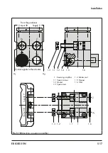
5-8
EB 8355-2 EN
Installation
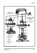
ly located in the bracket (11), fix the spring
included in the accessories at the back of the
positioner housing as illustrated in
.
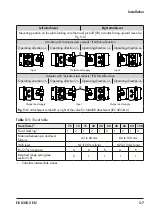
The positioner can be mounted either on the
left or right side of the control valve
(
). Turn the positioner at the adapter
housing by 180° to determine or change the
operating direction of the positioner/control
valve unit.
a) Mounting sequence
Î
Required mounting parts and accesso-
ries:
Î
See
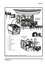
Valve with cast yoke
1. Screw the plate (3) to the stem connector
of the actuator and plug stems using the
countersunk screws.
Use the additional mounting bracket (15)
for 2100 and 2800 cm² actuators with
120 mm travel.
2. Remove the rubber stopper from the
adapter housing and fasten the adapter
housing either on the left or right of the
NAMUR rib using the hex head screw as
shown in
Valve with rod-type yoke
1. Screw the plate (3) to the follower clamp
of the plug stem.
2. Screw the studs (12) into the adapter
housing.
3. Place the adapter housing with the plate
(13) onto either the left or right valve rod
(
) and screw tight using the nut
(14). Make sure that the adapter housing
is at the correct height to mount the lever
(1) so that it is in a horizontal position
when the valve is at mid-travel.
4. Screw the pin (2) into the middle row of
holes on the plate (3) and lock it into po-
sition over the correct lever marking (1
or 2) as indicated in
5. Clamp the clip (4) onto the lever (1). The
clip must be clamped onto the lever (1)
with the open side facing downward
when the positioner is attached with the
air connection at the front.
6. Attach the lever (1) including clamping
plate (5) to the shaft (8), making sure
that the clip clasps the pin (2).
b) Initial adjustment of travel
1.
Move the valve to 50 % travel.
2. Move the shaft (8) in the adapter hous-
ing so that the black pointer (7) matches
the cast marking on the adapter housing.
3. Fasten the clamping plate (5) in this posi-
tion using the screw (6).
4. Screw the pin (10a) into the positioner
lever on the side where the press nut is
located. Lock it in position with the hex
nut on the other side, observing the
mounting position
A
or
B
according to
5. Place the positioner on the adapter hous-
ing, taking into account the mounting di-
rection. Fasten it, making sure that the
pin (10a) rests against the bracket (11).
2
1,5
1
7
8
5
15
14
3
2
2
4
3
6
1
L
12
13
11
9
A
B
10b
10a
Attachment to
NAMUR rib
Attachment to
rods
1
Lever N1, N2
2
Pin
3
Plate
4
Clip
5
Clamping plate
6
Screw
7
Pointer
8
Shaft
9
Lever of positioner
10a Coupling pin
10b Lock nut
11 Bracket
12 Studs
13 Plate
14 Nuts
15 Mounting bracket
Fig. 5-6:
Attachment according to IEC 60534-6 (NAMUR)
Summary of Contents for 3767
Page 10: ...1 6 EB 8355 2 EN...
Page 14: ...2 4 EB 8355 2 EN...
Page 58: ...6 2 EB 8355 2 EN...
Page 60: ...7 2 EB 8355 2 EN...
Page 70: ...10 2 EB 8355 2 EN...
Page 72: ...11 2 EB 8355 2 EN...
Page 74: ...12 2 EB 8355 2 EN...
Page 76: ...13 2 EB 8355 2 EN...
Page 78: ...14 2 EB 8355 2 EN...
Page 79: ...EB 8355 2 EN 14 3...
Page 80: ...14 4 EB 8355 2 EN...
Page 81: ...EB 8355 2 EN 14 5...
Page 88: ...14 12 EB 8355 2 EN...
Page 89: ...EB 8355 2 EN 14 13...
Page 90: ...14 14 EB 8355 2 EN...
Page 91: ...EB 8355 2 EN 14 15...
Page 92: ...14 16 EB 8355 2 EN...
Page 93: ...EB 8355 2 EN 14 17...
Page 94: ...14 18 EB 8355 2 EN...
Page 95: ...EB 8355 2 EN 14 19...
Page 96: ...14 20 EB 8355 2 EN...
Page 97: ...EB 8355 2 EN 14 21...
Page 98: ...14 22 EB 8355 2 EN...
Page 99: ...EB 8355 2 EN 14 23...
Page 100: ...14 24 EB 8355 2 EN...
Page 101: ...EB 8355 2 EN 14 25...
Page 102: ...14 26 EB 8355 2 EN...
Page 103: ...EB 8355 2 EN 14 27...
Page 104: ...14 28 EB 8355 2 EN...
Page 109: ......
Page 110: ...2 EB 8355 2 EN...
Page 111: ...EB 8355 2 EN 3...

