SAMLEX AMERICA INC. | 55
APPENDIX A
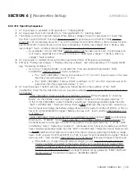
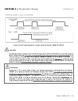
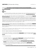
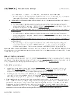
ii. Then, the phase of the Inverter voltage relative to the Generator voltage is tracked by 1º per cycle.
When the phase of the Inverter Section is within ± 10.5º of the Generator input voltage waveform,
the Transfer Relay is activated to transfer the AC load from the Generator to the Inverter Section at
zero crossing of the voltage waveform
b) Parameter SYNC GEN set at Option “0= Fine”
This setting is selected if
Grid / Inverter Generator
is connected to AC Input Terminals marked “GEN”
(7,8,9 in
Fig 2.3)
. Synchronization control logic used in this option is suitable for more stable frequency output of Grid
/ Inverter Generator. Under this option, the frequency and phase of the Inverter Section are synchronized with
the Grid as follows:
i. First, the frequency of the Inverter Section is tracked in steps of 0.1Hz per cycle and made equal to
the frequency of the Grid / Inverter Generator input.
i. Then, the phase of the Inverter voltage relative to the phase of the Grid / Inverter Generator voltage
is tracked by 1º per cycle. When the phase of the Inverter voltage is within ± 3.5º of the input
voltage waveform, the Transfer Relay is activated to transfer the AC load from the Grid / Inverter
Generator to the Inverter Section at zero crossing of the voltage waveform.
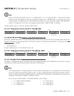
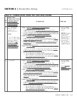
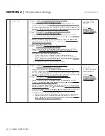
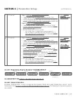
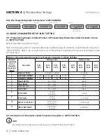
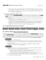
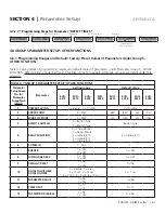
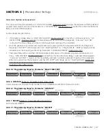
4.5.2.9.1 Programming Steps for Parameter "SYNC GEN"
Enter Key Up Key Enter Key Up Key x 8 times Enter Key
A N Y O P E R A T I N G
M O D E S C R E E N
ð
S E L E C T G R O U P
C H A R G E C U R V E
ð
S E L E C T G R O U P
I N P U T S E T T I N G
ð
D E F A U L T F R E Q
0 = 6 0 H z
ð
S Y N C G E N
1 = C o a r s e
ð
K E Y I N P A S S WO R D
0 0 0 0
Password 8052
See Section 4.3.1
ð
S Y N C G E N
1 = C o a r s e
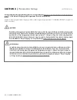
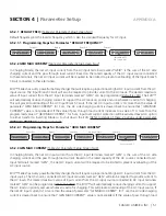
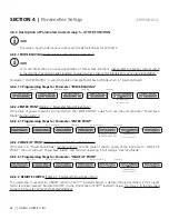
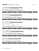
4.5.2.10 INPUT OC PROTECT
(Table 4.4, Parameter Setup Screen No.10)
If the net AC input current is 1A more than the value of GRID MAX CURRENT
(See Section 4.5.2.2)
or GEN MAX
CURRENT
(See Section 4.5.2.3)
for 1 sec, the AC side charging current is clawed back to ensure that GRID MAX
CURRENT / GEN MAX CURRENT value is not exceeded. If the value of pass through load current increases to a value
of 1A more than the programmed value of GRID MAX CURRENT / GEN MAX CURRENT for 5 sec, input over current
protection will be activated based on the following 2 options provided through parameter
INPUT OC PROTECT
:
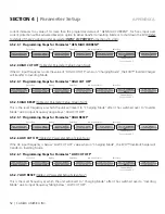
a)
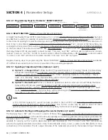
I N P U T O C P R O T E C T
0 = I N V m o d e
(This is the Default setting)
o
If the AC input current is 1A more than the programmed value of GRID MAX CURRENT / GEN MAX
CURRENT for more than 5 sec, the unit will switch over to Inverter Mode to ensure that AC power to
the load is maintained.
o
If the load reduces to 1A less than the programmed value of GRID MAX CURRENT / GEN MAX
CURRENT for 5 sec, switch back to Charging Mode
b)
I N P U T O C P R O T E C T
1 = S h u t d o w n
o
If the AC input current is 1A more than the programmed value of GRID MAX CURRENT / GEN MAX
CURRENT for more than 5 sec, Fault Mode will be activated:
•
There will be no AC output because the Transfer Relay will be de-energized, charging will be
stopped and PWM drive to the Inverter Section will be switched off
•
Fault message “Input over current” will be displayed on the LCD screen, Green LED marked
“Status” will be switched off and Red LED marked “Fault” will be switched on.
o
The unit will be latched in OFF condition and will require manual reset by powering off the unit, waiting
for 1 min and then, powering on again
SECTION 4 |
Parameter Setup

