14 | SAMLEX AMERICA INC.
APPENDIX A
SECTION 3 |
Operation
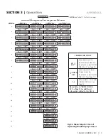
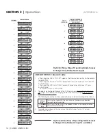
NOTES FOR FIG 3.2:
1. • The 3-digit No. XXX in “RC-XXX” indicates the Firmware Revision No. for the Remote Control EVO-RC
• The 4-digit No. XX.X in EVO-VX.XX denotes the Firmware Revision No. for the EVO™ Inverter/Charger
• The 4-digit No. XXXX in EVO-XXXX denotes the Model No. of Evolution™ Series Inverter/Charger
i.e. EVO-2212 / 2224 / 3012 / 4024
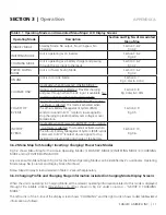
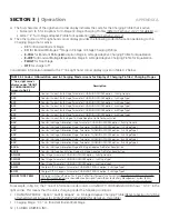
2. The display on the top right corner of the 19 Display Screens
(Display Screen Nos. 1 to 19)
under “CHARGING”
Mode
(Column 4, Group 3)
indicates the Charging Profile & the Charging Stage.
Refer to Section 3.6.2 & Table
3.2 for details.
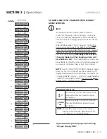
3. The following convention has been used to show up and down scrolling of the screens:
UP
ò
KEY
Press Up Key to scroll to the next screen in the downward direction towards higher Screen Nos
ñ
DOWN
KEY
Press
Down
Key to scroll to the previous screen in the upward direction towards lower Screen Nos
4. See Section 3.7 for information on Operating Mode Display Screens when the unit is in On-Line Mode
5. Parameter values shown in the screens are the default values for the 12V versions i.e. EVO-2212/3012.
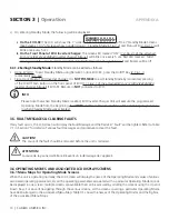
3.7 MENU MAPS FOR ON-LINE MODE SCREENS
i
INFO
Please refer to the following for additional information on "On-Line Mode":
• Section 4.8.5.2 of the attached Owner's Manual for EVO-2212/ 3012/ 2224/ 4024 for description and
application of "On-Line Mode"
• Section 4.4.2.13.2 for selecting programming option "1=On-Line" for On-Line Mode under
programming Parameter "MODE"
(Section 4.4.2.13)
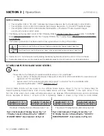
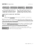
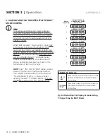
On-Line Mode Screens will be similar to the Off-line Mode Screens shown in Fig 3.2 for Menu Map for
Overall Operating Mode Screens. Each On-Line Mode Screen will show “ONLINE” in the right corner of the
first line of the screen. Each screen will alternate every 2 sec between Off-Line Mode Screen and On-Line Mode
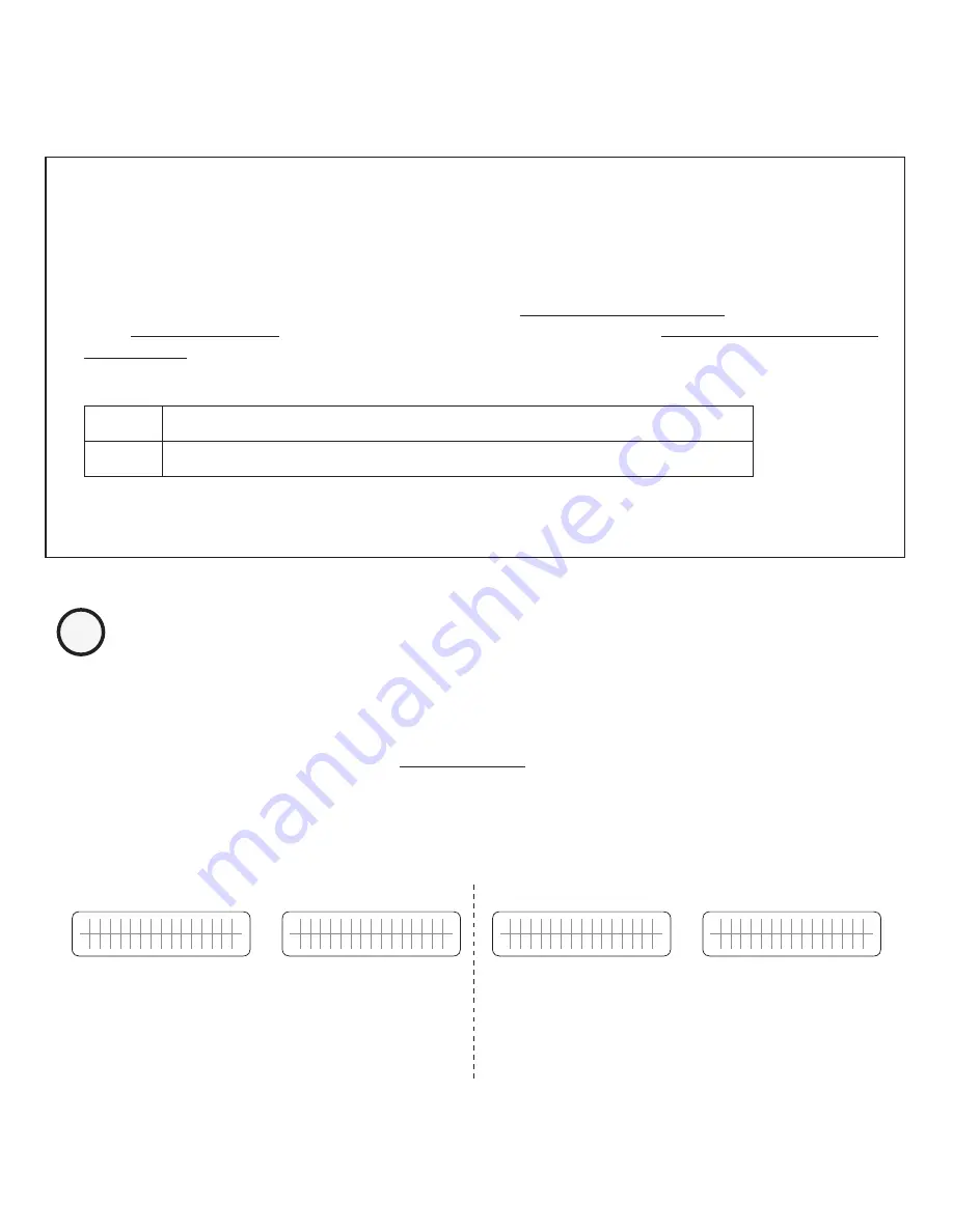
Screen. Examples of Screen 1 of each of the 4 Operating Modes is shown in Figs 3.3(a) to 3.3(d) below:
S T A N D B Y
B A T T E R Y 1 2 . 0 0 0 V
S T A N D B Y
O N L I N E
B A T T E R Y 1 2 . 0 0 0 V
I N V E R T I N G
O U T P U T
1 2 . 0 0 0 V
I N V E R T I N G O N L I N E
O U T P U T
1 2 . 0 0 0 V
The above 2 Display Screens alternate every 2 sec
The above 2 Display Screens alternate every 2 sec
Fig 3.3 (a) Example of Display Screen No. 1 of
7 Display Screens in Menu Map for “GROUP 1:
STANDBY MODE” (See Column 2 of Fig 3.2)
Fig 3.3 (b) Example of Display Screen No. 1 of
16 Display Screens in Menu Map for “GROUP 2:
INVERTING MODE” (See Column 3 of Fig 3.2)


