background image

Installation


User’s manual — 2900453/2

5

EN

3)

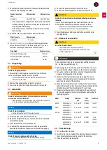
Check that the dynamic pressure of the machine feed water is 

within the following range of values: 

If the water pressure is higher than the maximum indicated, 

install a pressure regulator to set the pressure between 2.5 

and 4


bar (250 and 400


kPa).

If the water pressure is below the minimum value, install a 

back-up valve.

4)

Check the following values of the feed water flow rate:

5)

[Models without drain pump]

 Connect the drain pipe with an 

outer diameter of 30


mm to the drain line [

Fig.


1

/A]. For the 

maximum drain height, observe the following values:

2.3

Unpacking

1)

Remove the packaging that protects the machine. 

2)

Lower the machine from the pallet on which it is mounted.

2.4

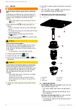
Assembly

1)

Screw the legs to the base of the machine. 

2)

Adjust the height of the legs so that the machine is stable and 

level with the ground.

3)

Place the machine at the installation site.

4)

Check that the tap water pressure is within the parameters 

specified in the previous chapter (use of the pressure gauge).

5)

Connect the water outlet hose to the drain point.

6)

Connect the water supply hose to the mains water point. 

7)

Insert the detergent and rinse aid inlet hoses into the corre

-

sponding bottles.

2.5

Electrical connection

1)

Before plugging in the machine, make sure that the mains volt

-

age matches the voltage indicated on the machine nameplate. 

2)

Set up the machine's electrical connections, depending on the 

model and configuration of the machine.

3)

Disconnect the electrical power supply: unplug the circuit-

breaker on the electrical panel corresponding to the external 

power supply socket of the machine.

4)

Make the electrical connection according to the type of model 

and electrical configuration of your machine, as explained in the 

attached document "Electrical diagram" for each case. 

5)

Prepare a residual current circuit-breaker with a sensitivity of 

30


mA and a magneto-thermal circuit-breaker as described in 

the following table:

2.6

First start-up

1)

Turn on the water stopcock. 

2)

Switch on the circuit-breaker of the electrical panel correspond

-

ing to the external power supply socket of the machine. 

3)

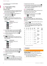
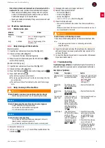
Place the overflow pipe in position

Dynamic water pres

-

sure

Minimum value

Maximum value

All models

2


bar (200


kPa)

4


bar (400


kPa)

Water flow rate

Minimum value

All models

15 L/min

Drain height

Maximum value

Models with drain pump (B) 

1,000


mm

Dome models without drain pump

500


mm

Other models

90


mm

⚠ 

Warning

Risk of trapping hands

There is a high risk of trapping your hands if you lift the ma

-

chine onto the base and place it on the ground.

– To move the machine from one place to another, hold the 

machine from the sides.

⚠ 

Warning

Risk of serious accidents if the machine cannot be 

disconnected or turned off

– When installing the machine, make sure the operator will be able 

to reach the switch and plug without difficulty. 

Notice

Risk of water leakage 

– Before installation, turn off the water stopcock.

Notice

Risk of hose clogging and/or choking

– Avoid making reductions with the hose when installing.

⚠ 

Caution

Risk of irritation due to chemical exchange and foam 

release

If you insert the detergent and rinse aid inlet hoses into the 

wrong bottles, the machine will produce excessive foam. 

– Pay attention to the labelling on the chemical hoses before 

inserting the hoses into the corresponding bottles. 

⚠ 

Caution

Electric shock hazard

– The machine must be connected to earth. 
– The machine has an external earth-connection screw 

with the symbol shown;

ℹ 

Information

The connections may only be accessed by qualified personnel 

[


Installation qualification


p.


3


],

Model

Voltage

Cable sec

-

tion

Total 

Power

Protection

AX-40

230V/50Hz/1~
220V/60Hz/1~

3 x 2.5 mm2

2.74 kW

16 A 2P

AX50

230V/50Hz/1~
220V/60Hz/1~

3 x 2.5 mm2

3.35 kW

16 A 2P

AX-100

230V/50Hz/1~
220V/60Hz/1~

3 x 6.0 mm2

6.75 kW

36 A 2P

400V/50Hz/3N~
380V/60Hz/3N~

5 x 2.5 mm2

6.75 kW

20 A 

(3P+N)

230V/50Hz/3~
220V/60Hz/3~

5 x 6.0 mm2

6.75 kW

25 A 3P

Summary of Contents for AX-50

Page 1: ...0437 1 96 2 AX 40 AX 50 AX 100 Glasswashers and dishwashers ACTIVE User s manual Lave verres et lave vaiselles ACTIVE Manuel de l utilisateur Gl ser und Geschirrsp lmaschinen ACTIVE Benutzerhandbuch...

Page 2: ...e AX 13 DE Benutzerhandbuch Active AX 23 EN Contact If you have any queries or problems with the machine please contact your dealer FR Contact Pour toute question ou tout probl me avec la machine cont...

Page 3: ...The machine has been designed for washing kitchenware and uten sils in the hospitality and catering sector communities and agri food industry Reasonably foreseeable misuse The use of this machine for...

Page 4: ...ion Check that the water line is less than 1 50 m from the intended location of the machine Electrical connections Before installation take note of the power input required by the machine 6 Technical...

Page 5: ...with a sensitivity of 30 mA and a magneto thermal circuit breaker as described in the following table 2 6 First start up 1 Turn on the water stopcock 2 Switch on the circuit breaker of the electrical...

Page 6: ...he Thermal lockfunction 1 Switch the appliance on by pressing the ON OFF button 2 To activate this function access the electronic board and set switch 1 to position 1 See the SW1 position last figure...

Page 7: ...r use when the pre set temperatures are reached in the boiler between 75 and 85 C depending on the program and in the tank between 50 and 65 C depending on the configuration At this point the light on...

Page 8: ...nt the surface of the heat ing element is subject to residual heat after use Avoid placing your hands close to the heating element after using the machine Warning Risk of food poisoning from washing a...

Page 9: ...ssem bly as described in step 2 4 3 Troubleshooting Troubleshooting qualification Troubleshooting for this machine is allowed by Sammic approved service companies and technicians Description of proble...

Page 10: ...ection order 2 Install the soap injection fitting through the hole at the rear Rinse aid dispenser Mains water dispenser 1 Check that the rinse aid tank is full 2 Start the machine and stop the wash r...

Page 11: ...an authorised waste management centre or through municipal waste disposal entities Comply with the applicable regulations You can obtain information about waste disposal and the location of your neare...

Page 12: ...Active AX Technical specifications 12 User s manual 2900453 2...

Page 13: ...s en option selon le mod le Mod le Marques commerciales et copyrights Sammic est une marque commerciale d pos e par Sammic SL 1 Informations relatives la s curit Usage pr vu La machine est con ue pour...

Page 14: ...l ments fournis Tuyau d alimentation Tuyau d vacuation l ments non fournis pour le montage m canique Tournevis plat Cl pipe n 10 Pince universelle Tenaille Manom tre l ments non fournis pour le monta...

Page 15: ...l endroit d installation 4 V rifier que la pression de l eau du robinet est conforme aux param tres sp cifi s dans le chapitre pr c dent utilisation du manom tre 5 Raccorder le tuyau de sortie d eau...

Page 16: ...2 Pour s lectionner la temp rature de la cuve appuyer sur la touche PROG Lorsque trois secondes s coulent sans que la touche PROG ne soit enfonc e la temp rature est s lectionn e et le voyant de cycl...

Page 17: ...ouche ON OFF 2 Pour activer cette fonction acc der la carte lectronique et placer les commutateurs 2 5 sur la position 1 ou la position 0 selon le tableau ci dessous Voir la position SW1 dans la der n...

Page 18: ...lectionner le type de cycle de lavage en appuyant sur la touche PROG chaque pression un cycle diff rent est s lectionn dans la liste des programmes Fig 2 b 3 4 3 Lavage 1 Appuyer sur la touche START p...

Page 19: ...longer les mains pendant trop longtemps Porter des gants imperm ables en caoutchouc pour vider ou nettoyer la cuve la main Attention Risque d irritation par la vapeur d eau haute temp rature la fin du...

Page 20: ...s bras de lavage sup rieur et inf rieur 4 Retirer le jeu de filtres complet Filtres de surface Fig 3 1 Filtre collecteur Fig 3 3 Filtre d aspiration Fig 3 4 Mod les avec pompe de vidange Filtre de vid...

Page 21: ...multan ment Remplacer la sonde de la chaudi re Erreur du mode thermal lock Si la machine ne passe pas la phase de rin age apr s 15 minutes de fonctionnement de la pompe de lavage le cycle s arr te et...

Page 22: ...u surpresseur au robinet d arr t et rac corder l autre extr mit au tuyau fourni avec la machine 5 Mise au rebut Emballage Pour mettre l emballage au rebut suivre les normes de protection environnement...

Page 23: ...Inhalt je nach Modell Modell Handelsmarken und Urheberrecht Sammic ist eine von Sammic S L eingetragene Handelsmarke 1 Sicherheitshinweis Bestimmungsgem e Verwendung Das Ger t wurde f r das Sp len vo...

Page 24: ...Installation notwendiges Werkzeug und Material Im Lieferumfang enthalten Zulaufschlauch Ablaufschlauch F r die mechanische Montage nicht enthalten Flachschraubendreher Steckschl ssel Nr 10 Universalza...

Page 25: ...nstallationsort auf 4 berpr fen Sie dass der Flie wasserdruck innerhalb der im vor herigen Kapitel angegebenen Parameter liegt Verwendung des Manometers 5 Schlie en Sie den Wasserablaufschlauch am Abf...

Page 26: ...um zwischen folgenden Sym bolen zu w hlen Einstellen der Wannentemperatur Sp len Einstellen der Kesseltemperatur Klarsp len Einstellen der Wannentemperatur Sp len 1 Das Symbol leuchtet auf und eines...

Page 27: ...die Elektronikplatine ver ndert oder dekonfiguriert wird muss das Modell ber den folgenden Abschnitt f r Ger teeinstellungen eingestellt werden 1 Schalten Sie f r den Zugriff auf die Elektronikplatine...

Page 28: ...l lampe auf dem Bedienfeld auf Dieser Vorgang dauert ungef hr 30 Minuten 3 4 Hauptbetrieb 3 4 1 Vorsp len 1 Entfernen Sie restliche Verschmutzungen und sp len Sie und sp len Sie die Teile ab bevor Sie...

Page 29: ...eizelements unterliegt nach der Benutzung einer Restw rme Halten Sie Ihre H nde nach der Benutzung des Ger ts Ent fernen und Reinigen der Filter Entleeren der Wanne vom Heizelement fern Warnung Risiko...

Page 30: ...Ansaugfilter Abb 3 4 Modelle mit Ablaufpumpe Ablauffilter Abb 3 5 5 Reinigen Sie Filter und Arme Entfernen Sie Speisereste und andere R ckst nde von den demon tierten Elementen Achten Sie besonders da...

Page 31: ...de aus Ausfall des Modus Thermal lock Wenn die Sp lpumpe nach 15 Minuten Betrieb nicht in die Klarsp l phase schaltet stoppt der Zyklus und die LEDS f r die Zyklusauswahl Abb 2 b blinken zusammen mit...

Page 32: ...ckverst rkers an den Absperrhahn und das andere Ende an den mit dem Ger t gelie ferten Schlauch an 5 Entsorgung Verpackung Richten Sie sich bei der Entsorgung der Verpackungen nach den geltenden Umwel...

Page 33: ...ns DE Abmessungen FR Dimensions IT Dimensioni PT Dimens es PL Wymiary AR Manual de usuario 2900453 2 33 ES Dimensiones EN Dimensions DE Abmessungen FR Dimensions IT Dimensioni PT Dimens es PL Wymiary...

Page 34: ...Active AX ES Dimensiones EN Dimensions DE Abmessungen FR Dimensions IT Dimensioni PT Dimens es PL Wymiary 34 Manual de usuario 2900453 2 Fig C AX 100 1 Fig D AX 100 2...

Page 35: ...aque lectronique IT Piastra elettronica PT Placa electr nica Manual de usuario 2900453 2 35 ES Placa electr nica EN Electronic board DE Platine FR Plaque lectronique IT Piastra elettronica PT Placa el...

Page 36: ...Active AX 36 Manual de usuario 2900453 2...

Page 37: ...Active AX 12 2900453 2...

Page 38: ...0 180 120 150 210 40 30 24 30 24 20 230 50 1 400 50 3 250 0 33 550 0 75 550 0 75 750 1 1200 1800 1800 2500 2500 2800 5000 6000 2750 3350 5555 6750 50 65 122 14 75 85 167 185 9 0 14 0 14 0 25 0 3 2 4 5...

Page 39: ...1 LED LED 4 4 4 4 1 4 4 2 10 1 DD EV1 2 1 2 5 6 PROG Sammic 10 fH 5 2012 19 EU WEEE Waste of Electrical and Electronic Equipment LED Description PRESOST PTE SEG LED Description M1 K2 R2 ON OFF C1 CAL...

Page 40: ...R 4 2 4 2 1 4 2 2 1 3 1 2 3 2 3 ON OFF 1 3 1 2 3 2 3 PROG 4 START 4 2 3 1 4 2 2 2 ON OFF 3 4 3 1 3 3 3 4 3 5 5 6 7 2 4 3 Sammic LED 4 2 2 9 4 2 3 9 Description LED 2 7 3 6 Thermal lock 15 LED 2 b 5 SV...

Page 41: ...Active AX 8 2900453 2 4 5 6 3 4 1 1 PROG START 2 5 4 3 4 1 60 1 4 2 5 3 6 1 2 3 4 5 6...

Page 42: ...ON OFF 2 Thermal lock 2 2 2 b 3 75 85 50 65 30 3 4 3 4 1 1 2 3 3 4 2 1 PROG 2 PROG 2 b 3 4 3 1 START START Thermal lock 2 3 1 ON OFF a 2 START b 3 PROG c d ON OFF Thermal lock 1 2 3 b a c d Descripti...

Page 43: ...RT Thermal lock 1 ON OFF 2 1 1 SW1 2 7 2 1 START 2 7 3 1 ON OFF 2 2 5 1 0 SW1 3 3 1 1 2 3 2 50 60 60 65 75 80 85 SW 2 SW 3 SW 4 SW 5 17 18 0 0 0 1 AX 40 3 19 20 1 0 0 1 AX 40 B 13 14 0 1 1 0 AX 40 90...

Page 44: ...5 1 2 3 4 5 30 2 6 1 2 3 4 3 5 B 1000 500 90 3 AX 40 230 50 1 220 60 1 3 x 2 5 2 2 74 16 2 AX50 230 50 1 220 60 1 3 x 2 5 2 3 35 16 2 AX 100 230 50 1 220 60 1 3 x 6 0 2 6 75 36 400 50 3 380 60 3 5 x 2...

Page 45: ...Active AX 4 2900453 2 2 2 1 2 2 10 F 1 50 6 11 1 1 2 GAS 3 2 5 4 250 400 4 A 30 AX50 B GAS A 30 mm AX50 C 2 200 4 400 15 A B AX 40 C A A B C AX 50 A B C AX 100...

Page 46: ...3 1 3 2 4 2 1 2 2 2 3 2 4 2 5 2 6 2 7 3 6 3 1 3 2 3 3 3 4 4 8 4 1 4 2 4 3 4 4 5 10 6 11 Active AX Active AX AX 40 B DD AX 50 B DD AX 100 B DD Sammic Sammic S L 1 Sammic 69 1 AX 40 2 5 AX 50 2 8 AX 10...

Page 47: ......

Page 48: ...10 22 2900453 2 ER 0437 1 96 AX 40 AX 50 AX 100 ACTIVE AR...

Reviews: