background image

SaMASZ Sp. z o.o. 

Poland, 15-161 Białystok, ul. Trawiasta 15 


Rok zało

ż

enia – 1984 


NIP 966-159-29-76 

tel. (+48) (85) 664-70-31 
fax (+48) (85) 664-70-41 

e-mail: [email protected] 

www.samasz.pl


OPERATOR’S MANUAL 


DOUBLE-SIDED DISC MOWER WITH 

CENTRAL SUSPENSION 


Standard 

On special order 


KDD 861 (H) 

- 28' 3" 

Wide swath 

KDD 860 (H) 

- 28' 3" 

Narrow 

swath 

KDD 941 (H) 

- 30' 10" 

KDD 940 (H) 

- 30' 10" 


KDD 861 S (H) 

- 28' 3" 

Wide 

conditioner 

KDD 860 S (H) 

- 28' 3" 

Narrow 

conditioner 

KDD 941 S (H) 

- 30' 10" 

KDD 940 S (H) 

- 30' 10" 


KDD 860 W (H) 

- 28' 3" 

Swath 

rollers


KDD 940 W (H) 

- 30' 10" 


KDD 861 S T (H) 

- 28' 3" 

Wide 

conditioner


KDD 860 S T (H)  - 28' 3" 

Narrow 

conditioner


KDD 941 S T (H) 

- 30' 10" 

KDD 940 S T (H)  - 30' 10" 


KDD 860 W T (H)  - 28' 3" 

Swath 

rollers


KDD 940 W T (H)  - 30' 10" 


IN272USA006 

2014.02.21 

EDITION NO 6 

Serial number: 

Summary of Contents for KDD 860 W

Page 1: ...der KDD 861 H 28 3 Wide swath KDD 860 H 28 3 Narrow swath KDD 941 H 30 10 KDD 940 H 30 10 KDD 861 S H 28 3 Wide conditioner KDD 860 S H 28 3 Narrow conditioner KDD 941 S H 30 10 KDD 940 S H 30 10 KDD 860 W H 28 3 Swath rollers KDD 940 W H 30 10 KDD 861 S T H 28 3 Wide conditioner KDD 860 S T H 28 3 Narrow conditioner KDD 941 S T H 30 10 KDD 940 S T H 30 10 KDD 860 W T H 28 3 Swath rollers KDD 940 ...

Page 2: ... DISCS HAVE COME TO COMPLETE STANDSTILL DO NOT OPERATE WHEN ANY PERSON REMAINS IN THE DANGER AREA 164 1 WARNING Keep this manual for future use Optimum inclination towards the ground is 0 5 to the mowing direction It is allowed to work in horizontal position Different inclination may damage the mower 0 5 ...

Page 3: ...ydraulic system 18 4 8 4 Forbidden actions 18 4 8 5 Residual risk assessment 18 4 9 Safety labels and their meaning 18 4 10 Design and operation of safety breakaway device 23 5 OPERATION 24 5 1 Attaching the mower to the tractor 24 5 1 1 Connecting hydraulic hoses 25 5 1 2 Mounting PTO shaft 26 5 2 Control panel 27 5 2 1 Setting mower in transport position on headlands 28 5 2 2 Setting mower in ve...

Page 4: ...er conditioners driving chain 44 6 7 3 Daily maintenance 44 6 7 4 After season maintenance and storing of machine 45 6 8 Conveyor control and adjustment 45 6 8 1 Cleaning belts and rollers 45 6 8 2 Conveyor belt replacement and adjustment instruction 46 7 LUBRICATION 48 7 1 Cutterbar 48 7 2 Intersecting axis gears 49 7 3 Roller conditioner s gearbox 50 7 4 Chain drives of the roller and the scarif...

Page 5: ...rates this mower It should be kept near the mower for future use If the mower is used by another operator it should be in working condition and include this operator s manual and all other basic equipment Operator s manual is attached to every machine in order that the operator can familiarize himself with design working principles service and adjustment of the mower The operator should be familia...

Page 6: ...r mounted disc mower with tine roller conditioner is intended to mow green fodder such as grass and alfalfa on permanent grassland pastures on crop fields without rocks and to form loose rows of cut forage As a result of the passing of the layers of the green fodder through the flails or rollers the grass stems are broken and a layer of wax is removed This facilitates and speeds up the drying proc...

Page 7: ...overrunning clutch 1100 Nm Cutting speed of the knife 86 2 m s Disc rpm 3078 rpm Emitted noise up to 115 dB Productivity depends on tractor s real working speed max working speed is not specified by SaMASZ company Applies to operation at V 12 km h Noise measured by noise from 3 3 distance from the machine in motion in final test area Tab 2b Specification of the mower wide and narrow tine condition...

Page 8: ...company Applies to operation at V 12 km h Noise measured by noise from 3 3 distance from the machine in motion in final test area Mower with hydro pneumatic support Tab 2d Specification of the mower roller conditioner Standard Swath rollers Model KDD 860 W KDD 940 W KDD 860 W T KDD 940 W T Working width 28 3 30 10 28 3 30 10 Number of knives pcs 28 32 28 32 Tractor PTO rpm 1000 rpm Tractor power r...

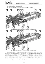
Page 9: ... tractor s rpm is transmitted through intersecting axis gear 3 on PTO shaft 6 which through intersecting axis gear 7 drives the cutterbar 4 On the cutterbar 4 there are discs with two knives each Hydraulic cylinder 2 is used to adjust the mower to working position The mower s power is supplied by the outer hydraulics of the tractor Main frame 11 on which the cutterbar is situated is supported by t...

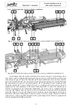
Page 10: ...ntersecting axis gear 6 PTO shaft 8 intersecting axis gear 7 and chain gearbox 9 is transmitted to tine conditioner 12 Hydraulic cylinder 2 is used to adjust the mower to working position The mower s power is supplied by the outer hydraulics of the tractor Main frame 11 on which the cutterbar 4 is situated is supported by the springs 8 Additionally the mower can be equipped with belt conveyors 15 ...

Page 11: ...er conditioner 14 Hydraulic cylinder 2 is used to adjust the mower to working position It is supplied from outer hydraulics of the tractor Main frame on which the cutterbar 4 is situated is supported by the springs 8 On top of roller conditioner s safety guard there are swath guides 5 mounted 3 2 4 Belt conveyors Fig 4 Hydraulic system of belt conveyors Fig 5 Belt conveyor Additionally the mower c...

Page 12: ... enables the mower s impact to the ground to be controlled by modification of the pressure in hydraulics 3 3 Standard equipment and spare parts The mowers are sold with the following standard equipment warranty card operator s manual with spare parts list knife L 105 180 pcs PTO shaft cutting disc with drum 2 pcs spray paint 150 ml warning safety labels and operator s manual cutting disc 2 pcs dis...

Page 13: ... 50 shaft operating hours Fig 7 If access holes are accessible lubricate fittings through access holes Fig 7 PTO shaft lubrication points Mounting directions PTO shafts of other brands with equivalent parameters could be used after first obtaining SaMASZ permission NOTE Optional extra equipment should be ordered separately The mower is equipped with optional equipment such as holders and brackets ...

Page 14: ...ator When using servicing repairing moving or storing the machine the operator must wear safety footwear safety gloves plus ear protection and dusk mask if necessary During use the machine may give rise to dust especially if the soil is dry You are advised to use a tractor with a cab fitted with filters in the ventilation system Failing this wear a dust mask with filter to protect your respiratory...

Page 15: ...wer when the mower blades are off the ground Before you start the tractor make sure that all drives are turned off and the levers that turn the hydraulics are in neutral position Never leave tractor s engine running without supervision Before you leave the tractor turn off the engine and remove the key from tractor s ignition DO NOT operate the mower when driving the tractor backwards Permissible ...

Page 16: ... pinched or crushed by some of its parts Take extra care when carrying out these maneuvers and have all persons keep well clear of the danger zone Do not change position of the mower until there are no people or animals around pay particular attention to children While transporting the mower put a warning plate with combined lights and reflectors and warning triangle on the mower During transport ...

Page 17: ...es When mounting slings chains handles etc always set the machine s center of gravity properly To safely support the machine use ropes of adequate length so that the angle between them is no greater than 120 and the angle between the strand and the vertical is no greater than 60 Lift the machine with the utmost caution and move it slowly No one should be within the range of action of the lifting e...

Page 18: ...ar manufacturer s manual placed on the bar Follow all safety precautions in that manual Use only PTO shafts recommended by mower s manufacturer with guards in good condition In order to operate safely use only undamaged PTO shafts and shields Damaged PTO shafts and shields must be repaired or replaced with new ones before use 4 6 Hydraulic assembly Hydraulic assembly is under high pressure Hydraul...

Page 19: ...ation and maintenance are unavoidable A major source of risk that could result in serious injury or death can occur during the performance of these operations Major source of risk follows performance of these operations operation of mower by minors operation by individuals who have not read the operator s manual and safety labels operation of mower by persons under influence of alcohol or other su...

Page 20: ... the art in technology on the date it was manufactured 4 8 5 Residual risk assessment Residual risk occurs from not complying with the instructions and safety precautions Such risk can be minimized by doing the following thorough familiarizing yourself with operator s manual allow no persons on the machine when operating allow no persons within the mower operation range adjust maintain and lubrica...

Page 21: ...son is within the danger area of 164 N 9 Caution rotor N 23 Watch out power lines N 40 Signs indicating transport holders N 48 Stay a way from mower s inclination area N 49 Never stand near tractor s 3 point linkage while steering tractor s lift N 50 Do not stay in the swinging area of mower s parts N 206 Wear protective gloves N 117 Avoid fluid escaping under pressure Consult technical manual for...

Page 22: ...uble sided disc mowers with central suspension 20 N 30 Cutterbar Perfect Cut N 150 N 213 for KDD S SL N 31 N 53 N 55 N 75 N 77 Tension of conveyor s belt N 79 On conveyor decal N 80 N 115 Locking conveyors N 96 N 108 N 60 ...

Page 23: ...Operator s manual Double sided disc mowers with central suspension 21 N 63 Use the required Personal Protective Equipment N 109 Fig 11a Warning decals placed on the mower without conditioner ...

Page 24: ...Operator s manual Double sided disc mowers with central suspension 22 Fig 11b Warning decals placed on the mower with conditioner Fig 11c Warning decals placed on the mower with roller conditioner ...

Page 25: ...part used for repair of the mower should have all warning decals provided by the manufacturer 4 10 Design and operation of safety breakaway device Hydraulic safety breakaway device protects mower against hitting small obstacles In the event the mower hits an immovable obstacle the cutterbar folds back about 30 degrees and at the same time rises about 2 4 After that the cutterbar automatically come...

Page 26: ... adjusted to be attached to the tractors with 3 point linkage Cat II and III The mower is connected to tractor s 3 point linkage Fig 14 Before hitching or unhitching the machine to from tractor s 3 point make sure that the control lever position prevents the machine from being accidentally raised or lowered After the mower has been attached adjust on flat ground mower s position by means of top S ...

Page 27: ...ulic hoses to tractor as follows yellow A green B and red C see decal N 108 Fig 16a in separate sections of tractor s hydraulic assembly Fig 16b Fig 16a Hydraulic hoses mower tractor Make sure that the hydraulic hoses have been inserted properly and that the colours of the hoses match Make sure that there are no leaks in the hydraulic system and that the connections have been correctly made WARNIN...

Page 28: ...ast as long as possible CAUTION If need be shorten the PTO haft according to its operator s manual given by the shaft s manufacturer Fig 17 Fig 17 Instruction of PTO shaft shortening CAUTION Handle all parts with utmost care Never place your hands or fingers between one part and the other Wear safety clothes such as gloves protective footwear and goggles The operation of shortening must be carried...

Page 29: ... sections and control panel located in the tractor s cabin The action to be performed is chosen by the operator with buttons on the panel which controls the tractor s hydraulics Push the button 1 Fig 18 in order to enable controlling Pushing the button is signalled with a diode located over the button Fig 18 Control panel functions 1 Control on off switch 11 Left cutterbar lifting 2 Information sc...

Page 30: ...gnalled with a red diode located over the button which corresponds to the cutterbar In order to unlock a particular cutterbar push either buttons 13 or 14 again unlocking cutterbar protection is then signalled by dimming of the red diode 5 2 2 Setting mower in vertical transport position In order to set mower in vertical transport position Fig 23 push button 5 If near the end of lifting phase and ...

Page 31: ...ease do the following lift the mower with tractor hydraulic lift until the lower lift pins of the mower 3 point linkage frame raise about 1 8 above the ground Fig 23 lower the transport height on the tractor links so it does not exceed 13 2 Fig 23 lift support legs S and block them with cotter pins Fig 20 before putting the mower in transport position block transport lock Fig 21 NOTICE Unblocking ...

Page 32: ...ds WARNING Legal requirements for transport on public roads may differ from state to state Check your location s requirements and comply To comply with safety precautions concerning transport on the public roads the mower should be equipped with the following devices portable warning light plates to be mounted on both sides of mower top guard in their holders see Fig 24 The panel consists of warni...

Page 33: ...to a horizontal position using the tractor s lever slowly lower the cutterbar to the horizontal position unblock the lock and lower the mower until the cutterbar touches the ground by means of link S Fig 14 adjust the cutting height Extending the link S increases the cutting height and shortening the link reduces it 5 6 Preparing mower for operation mower with hydro pneumatic support NOTICE Before...

Page 34: ... of the mower will cause increase of cutterbar pressure on the ground which will lead to faster wear of sliding skids overload of cutterbar higher fuel consumption damage to the stubble and contamination of the fodder 5 7 Preparing the mower for work Put the mower into operation when the cutterbar is on the ground so that oil can fill the whole cutterbar When the mower is in working position pleas...

Page 35: ... Pressure on the ground is regulated by changing the tension of support springs Decreasing the pressure of the cutterbar on the ground is done by increasing the tension of the support springs from moving the lock in the next hole on the rod towards the springs Fig 26 Increasing the cutterbar s pressure on the ground is done by decreasing the tension of support springs from moving the lock towards ...

Page 36: ...ich makes an impression of inaccurate mowing Every mower may leave stripes of uncut grass when it comes to the knives which cut the grass towards the grass direction It is a normal phenomenon Practically it is not possible to achieve such attractive stubble as in 2 drum mowers because the knives work horizontally or at an angle of up to 8 to the ground and when it comes to 2 drum and 4 drum mowers...

Page 37: ...nife mounting to get the best results In case of mowing soft meadows the pressure of the cutterbar on the ground should be reduced by adjusting support springs Always check to make sure that the ground speed suits the conditions or work and that it does not create a potential source of danger Do not take sharp turns anytime and do not operate in reverse 5 8 2 Mower clogging When operating the mowe...

Page 38: ...rizontal position may cause faster wearing rusting of the cylinder from the inside through vent valve by being penetrated by moisture from the air Fig 28 Double sided disc mower in its storing position 6 MOUNTING AND ADJUSTMENTS 6 1 Mounting and timing of the knives The knives should be mounted as shown in Fig 29 The knives recommended by the manufacturer have dimensions of 105x49x4 and comply wit...

Page 39: ...time could cause serious damage to the cutterbar WARNING When replacing knives the engine must be stopped and the cutterbar must lie on the ground PTO shaft must be disconnected Discs should be perpendicular to cutterbar Fig 30 Quick replacing of the knives with mounting lever 6 3 Adjusting the cutterbar Swath width is adjusted with swath guides mounted on the 3 point linkage frame of the cutterba...

Page 40: ...S T H KDD 941 S T H KDD 860 S T H and KDD 940 S T H loosen eye screw 2 of the swath guide set the swath guide 1 as needed tighten screw 2 even spreading of swath might be adjusted with wheels 3 the same as it is preformed with guides Fig 32 Adjustment of swath guides 1 swath guide 2 adjustment screw 3 swath wheel In order to set swath width adjustment of swath guides 1 should be performed Fig 33 f...

Page 41: ...ION Improper mounting of the knives will block the mower When mounting pay particular attention to the direction of disc s rotation shown below KDD 861 H wide swath right cutterbar KDD 861 H wide swath left cutterbar KDD 941 H wide swath right cutterbar KDD 941 H wide swath left cutterbar Fig 34a Narrow swath widths of SaMASZ disc mowers Disc without the forming drum Disc with the forming drum 1 2...

Page 42: ...aft Models KDD 861 S H KDD 860 S H KDD 941 S H KDD 940 S H KDD 861 S T H KDD 860 S T H KDD 941 S T H KDD 940 S T H Depending on size and thickness of the mowing grass it may be necessary to adjust the conditioner s mask The higher and thicker the grass the bigger the space between the conditioner s mask and its shaft should be Proper adjustment should be based on experience in so as not to block t...

Page 43: ... of grass conditioning adjust the conditioner s shaft rotary rate It can be adjusted within the range of 700 1000 rpm To increase the shaft s rotary rate switch lever A Fig 36 from I to III Set the lever in middle position II to stop the shaft WARNING Adjustment should be performed with PTO shaft s drive off Fig 36 Lever for adjusting conditioner s shaft rpm increasing plate conditioner clearance ...

Page 44: ...t well balanced Not keeping the shaft well balanced may lead to premature wear of the bearings and the shaft Replacement of flails 3 consists of unscrewing of nuts 2 removing bolts 4 and mounting brand new flails 3 Fig 37 NOTE A new bolt M16 65 oc cl 10 9 and nut M16 oc cl 8 should be used to make the connection torque down until tight Fig 37a Parts of tine conditioner narrow swath for mowers KDD ...

Page 45: ...of springs S Fig 38 by means of nut N Adjustment should be done on both sides of the conditioner Fig 38 Adjusting force of the pressure of roller conditioner 6 7 Maintenance and service 6 7 1 Checking the knives and knife holders All knives should have the same lengths and weights Always check mower before starting work for damaged missing and or worn knives Replace them if necessary only in sets ...

Page 46: ...ving shaft is transmitted by chain onto conditioner s or rollers axis Constant chain tension is provided by tensioner adjusted with tensioning bolt N Fig 40 Properly tensioned chain after being pressed with finger on tensioner end K Fig 40b should deflect by approx 0 2 KDD 860 W H KDD 940 W H Fig 40 Adjusting the tension of conditioner s driving chain view without part of the safety guard a tine c...

Page 47: ... in roofed places inaccessible to unauthorized personnel or animals If the machine is stored for a long period of time before first operation its technical condition should be examined and special attention should be paid to the hydraulics and the drive Paint the area where the paint is missing hydraulic hoses checked and lubricated Additionally remove any traces of rust and paint the area check t...

Page 48: ...2 Removal of impurities inside the conveyor 6 8 2 Conveyor belt replacement and adjustment instruction Mower KDD 860 940 with conveyors must be suspended onto tractor Lean the mower with use of upper connector cylinder as far as you can to the front in order to increase the distance between conveyor and the ground I The adjustment of the belt conveyor should be done only when the conveyor is in it...

Page 49: ...e between conveyor and the ground is approx 3 3 1 Loosen screws M10 S1 nuts M12 N2 adjustment screws M12 S2 of front tensioners Fig 44 Fig 44 2 Dismount front belt in lower part of the conveyor P Fig 45 Slide belt T down Fig 46 Fig 45 Fig 46 3 Clean and check condition of bearings in rollers worn ones must be replaced Driving roller hydraulic engine do not adjust 1 measure S1 S2 N S2 S1 N2 S1 S2 N...

Page 50: ...asure using angle bars 4 Start the mower and in particular hydraulic drive gradually increasing rpm from 0 to 1250 rpm 5 Adjust with screws S2 locking screws S1 each time to be repeated until fine tuned so there are no bulges on the belt IMPORTANT Precision is recommended so belts and their edges work symmetrically on rollers Well adjusted belts cannot bulge in places where v belt is guided inside...

Page 51: ...is on the ground Removing the old oil from the gearbox is done through the outlet C Fig 49 Intersecting axis gears oil Tab 7 Oil capacities in intersecting axis gears Model Oil capacity l Oil type Lubrication frequency All type 1 SAE 80W 90 API GL 4 Once every 3 seasons if working intensively more frequently Gears 52 01 0100AB L 53 01 0100AB L mowers KDD 941 ST KDD 861 ST 2 5 SAE 80W 90 API GL 4 O...

Page 52: ...e ground Removing the old oil from the gearbox is done through the outlet C Tab 8 Oil capacities in roller conditioner s gearbox Fig 50 Roller conditioner s gearbox lubrication points Fig 51 Bearing lubrication point with LT43 grease 7 4 Chain drives of the roller and the scarifier On Fig 52 are shown openings through which the chains of the chain drives can be lubricated These points are addition...

Page 53: ...igned to lubricate rolling and slide bearings that work in 30 to 130o C and main joints of the mower with STP grease and all connections in cylinders Fig 55 with STP lubricant Fig 53 Bearing lubrication point withLT43 grease Fig 54 Bearing lubrication point with LT43 grease Fig 55 Lubrication point of the suspension with STP grease Lubrication point Lubrication point Lubrication points Lubrication...

Page 54: ...cks the mower lack of grass flow or the flow is uneven Too low work speed Speed up to 10 km h or more Safety device is working often without clear reason Worn elements of safety device or improper adjustment This repair must be done by SaMASZ service Mower does not work even though the drive is transmitted from the tractor Damaged intersecting axis gear Replace intersecting axis gear Mower is bloc...

Page 55: ... for two years from the date of sale to the purchaser stated above 3 Any repair which is subject to warranty should be carried out by an authorised SaMASZ dealer Upon completion of the repair the dealer must submit a warranty claim within 14 days 4 Warranty claims regarding replacing of the product are considered if received within 14 days after it is completed by the manufacturer 5 The following ...

Page 56: ...ver plates c damage caused by accidents running into obstacles or other events for which the warrantor is not responsible d use of different knives not original SaMASZ knives e negligent maintenance f use of non genuine spare or replacement parts that are not specifically designed for the model in question g lack of needed records in the warranty card or filling in the warranty card independently ...

Page 57: ... disc mowers with central suspension 55 11 2 Warranty repairs record Repairs description and changed spare parts Date stamp and signature of repair shop Date stamp and signature of repair shop Date stamp and signature of repair shop ...

Reviews: