


Operator's manual
Two-rotor in-line rake
DUO 680
DUO 740
- 4 -
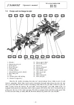
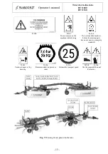
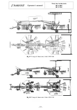
3.2. Design and working principle
Fig. 3.
Parts of
DUO 680
two-rotor rake
Drawbar (
1
) enables mounting the rakes on 3-point linkage beam, which is part of each
tractor's equipment. Drive from tractor rpm is transmitted through intersecting axis gear (
2
) onto
rotary gear with shaft located on rake's front linkage (
16
). Rear rotor gear (
21
) is driven by gear (
2
),
roller located inside the linkage (
5
) and roller with homo-kinetic joint (
18
). Both rotors are
equipped with numerous raking arms (
8, 3
). Safety guards (
13
) reduce the risk of unwanted objects
getting into the area of rotor arms operating. The rake is equipped with adjustable swath guard both
on front and rear raking assembly (
20, 15
). Both assemblies are guided onto carts (
14, 19
).
1 – Drawbar
2 – Intersecting axis gear
3 – Safety guard
4 – Front rotor gear
5 – Joint linkage
6 – Turning cylinder
7 – Ground following lock cylinder
8 – Rear raking arm
9 – Tine
10 – Warning plate with lighting
11 – Drawbar's support leg
12 – Front support wheel
13 – Front safety guard
14 – Front cart
15 – Front swath guard
16 – Front linkage
17 – Rear support wheel
18 – Wide-angle shaft
19 – Rear cart
20 – Rear swath guard
21 – Rear rotor gear
6
7
8
20
19
17
15
12
11
13
1
5
10
4
21
14
2
9
3
18
16