


Tel: 886. 909 602 109 Email: [email protected]
www.salukitec.com
29
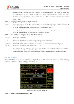
Users can set the phase shift between two orthogonal reference signals through the keyboard. The accuracy of
phase is 0.01°and the range is from -180° to +180°.
For phase, it’s meaningful only when there is a reference. In the system, the default reference phase is the phase of
REF IN after locked by a high precision PLL. Other phases are relative to this reference phase.
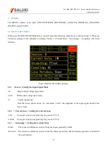
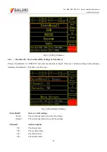
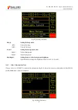
3.2.2 < Ref. source>: Setting the Reference Source
<External> The external reference signal.
<Internal> The internal reference signal. In this mode, the reference signal is from the internal oscillator. The
[REF IN] signal is useless
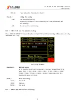
3.2.3 < Freq>: Setting the Internal Reference Frequency
When <Internal> is chosen in <Ref. source>, this setting can access. The frequency range is from 10mHz to 120
kHz and the default frequency is 1.000 kHz. Users can set frequency through the knob and the left and right buttons.
The minimum resolution of frequency is 1mHz.
3.2.4 < Slope>: Setting the External Signal Mode
When <External> is chosen in <Ref. source>, this setting can access. Choose the corresponding signal type
according to the actual external reference signal.
<TTL>
Choose TTL when the external reference signal is a square wave.
<Sine>
Choose Sine when the external reference signal is a sine wave.
If the external reference signal is TTL logic, choose <TTL>. Pay attention that, even if the REFIN is a square wave,
it may still obtain an unsteady trigger because the level does not satisfy the threshold condition of the TTL logic.
Thus, it is beneficial to choose <Sine> to trigger. Moreover, choose TTL signal if the signal frequency is very low
(<1Hz).
If the input reference signal is sine wave, choose SINE to trigger. In this mode, the instrument will do precision
truing for the REF IN input and then detect the frequency and phase information.
Otherwise, the system has no requirement on the signal duty cycle no matter what the trigger way is. It is kind to
use common 50% duty cycle.
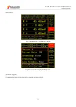
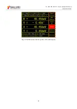
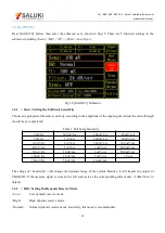
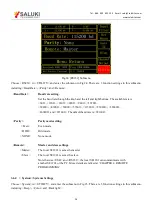
3.2.5 < Harmonic>: Setting the Harmonic Detection
Spinning the knob and press the left and right buttons under the knob to set the harmonic order required. The range
of harmonic order is from 1 to 32767 with default 1. The harmonic order is limited by (Harmonic* Freq)
≤
120kHz.
Here, Freq indicates the frequency of reference. Once beyond the limit, the system will not be able to continue to
increase the harmonic order.
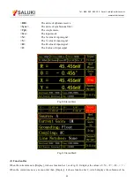
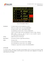
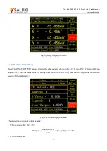
For example, the input signal is 1kHz square wave. Suppose that the signal’s amplitude is A. Set <Harmonic>as 1,
3, 5, 7…, the R will be 0.45A, 0.15A, 0.09A, 0.064A…respectively. This sequence is A times higher the
coefficient sequence of the square wave Fourier Series.