


Tel: 886. 909 602 109 Email: [email protected]
www.salukitec.com
28
Generally, choose <Ground> when the current of the input signal is not large. It prevent signal drift
caused by floating. Choose <Float> when there is a large potential difference between the signal
ground and chassis ground and a strong current injection. This can limit the current and protect the
system circuit.
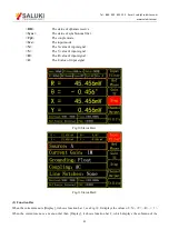
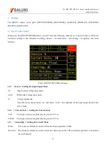
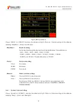
3.1.4 < Coupling >: Setting the Coupling Input Mode
<AC>
AC coupling input mode. In this mode, the DC component of the input signal will be eliminated. If
the signal frequency is greater than 200 Hz, <AC> should be selected.
<DC>
DC coupling input mode. In this mode, the AC component of the input signal will be eliminated. If
the signal frequency is less than 200 Hz, <DC> should be chosen.
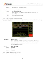
3.1.5 < Line Notches >: Setting the Status of the Notch Filters
<None>
Turn off all notch filters.
<Line>
Turn on the 50\60 Hz notch filter to suppress the power line interference.
<2xLine>
Turn on the 100\120 Hz notch filter to suppress the second harmonic interference of power.
<Both>
Turn on the 50\60 Hz and the 100\120 Hz notch filter.
Generally, if the signal frequency is greater than 200Hz, choose <Both>, <Line> or <2×Line>.
Otherwise, choose <None> to avoid the amplitude damage due to small slope of the notch filter.
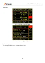
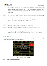
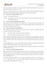
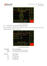
3.2 [REF/PHASE]
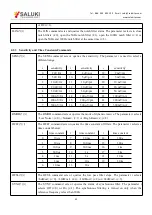
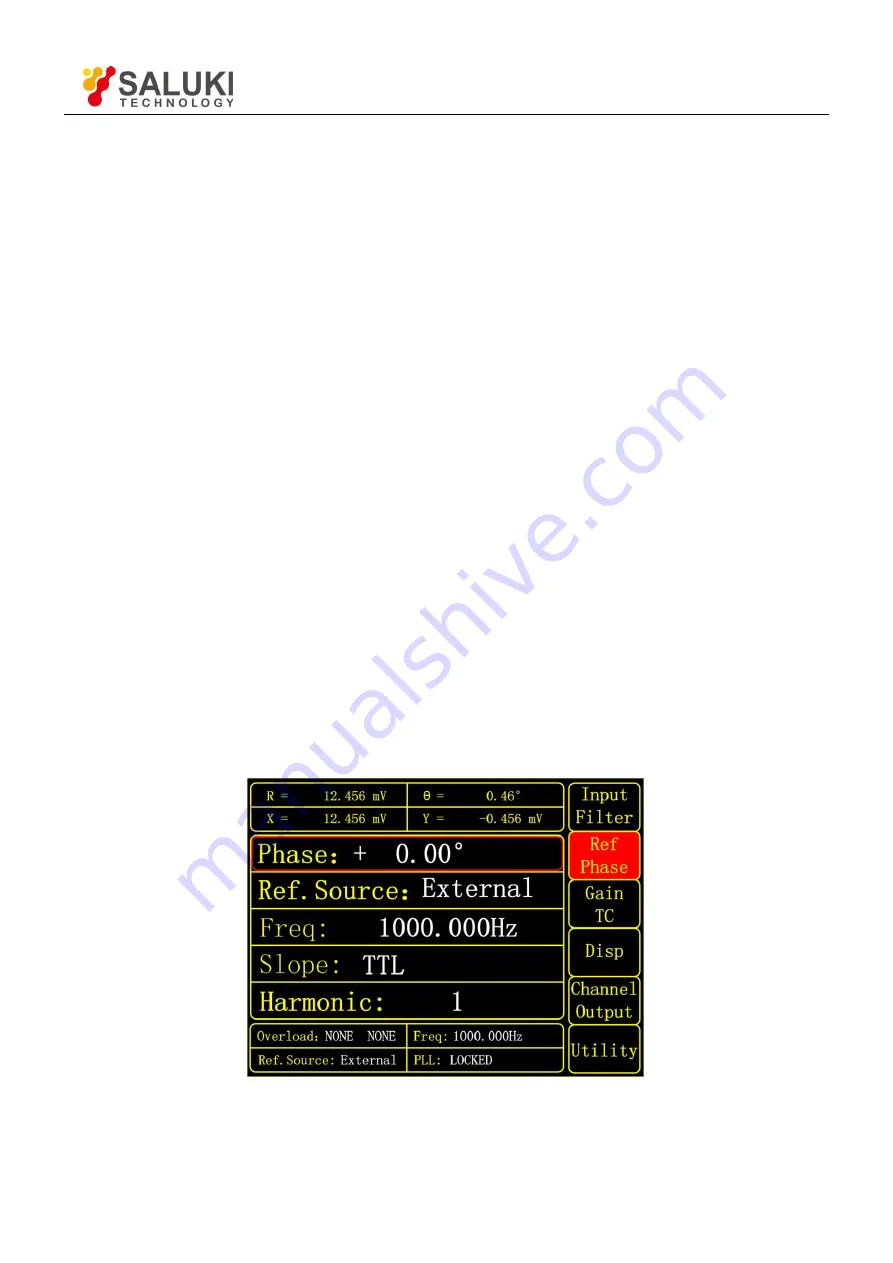
Press [REF/PHASE] and enter its submenu, see Fig.17. There are 5 function settings in the submenu, including
<Phase>, <Ref.source>, <Freq>, <Slope> and <Harmonic>.
Fig.17 The [REF/PHASE] Submenu
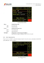
3.2.1 < Phase >: Setting the Reference Phase