24
Ŗ
In equipments with separate bypass line, a galvanic
isolation transformer has to be installed in any of the
two lines that supply the UPS (rectifier input or static bypass),
to avoid the direct union of the neutral of both lines through
the internal wiring of the equipment.
This is applicable when the two lines are supplied from dif-
ferent mains, i.e.:
Two different electrical companies.
An electrical company and genset, ...
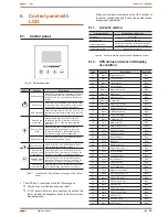
Cable as bridge
mode "Jumper"
factory installed
default
UPS TWIN RT > 3 kVA with no bypass line.
SAI TWIN RT > 3 kVA with bypass line.
Frequency converter TWIN RT > 3 kVA.
Fig. 13.
Power block connection depending on the
equipment.
4.3.3. Connection of the IEC outlets and
output power blocks.
Ŗ
As this is a device with class I protection against elec-
tric shocks, it is essential to install a protective earth
conductor (connect earth(
)
). Connect the conductor to
the terminal, before connecting the power supply to the input
power block.
Ŗ
All the equipments have female IEC outlets, in greater or lesser
numbers depending on the power rate of the equipment:
Models up to 2 kVA: 2 groups of 4 IEC outlets of 10A labelled
as LS1 and LS2, which can be set through the control panel
and/or Win Power.
Models of 3 kVA: 2 groups of 4 IEC outlets of 10A labelled
as LS1 and LS2, which can be set through the control panel
and/or Win Power, plus a IEC connector of 16A.
Models from 4 to 6 kVA: 2 groups based on 2 IEC outlets of
10A and 1 of 16A each one.
Each group has an automatic protection switch. In case
of tripping, the load connected to the respective outlet
has to be checked, otherwise the protection will be acti-
vated and deactivated cyclically, and therefore the loads
will suffer the consequences.
Models of 8 and 10 kVA: 4 groups based on 2 IEC outlets of
16A each one.
Each group has an automatic protection switch. In case
of tripping, the load connected to the respective outlet
has to be checked, otherwise the protection will be acti-
vated and deactivated cyclically, and therefore the loads
will suffer the consequences.
Ŗ
For hardwired equipments (models from 4 to 10 kVA).
Connect the loads to output power block
U (L)
and
N
, by
respecting the phase and neutral rotation stated in the la-
belling of the equipment and this manual (see figure 13).
When discrepancies exist between the labelling and the
instructions of this manual, the labelling will always prevail.
Loads can be connected to the IEC outlets, to the
output power blocks or to both at the same time,
meanwhile the features of the equipment and IEC outlets
limitations are not exceeded, otherwise there will be
sudden blackouts in the power supply of the connected
loads at the output.
Ŗ
If besides of the critical loads, it is required to connect lag-
ging loads of high consumption, like laser printers or CRT
monitors, the inrush currents of these peripherals will be kept
in mind in order to avoid blocking the equipment under the
worst conditions.
It is better to not connect the loads of this kind, due to the high
quantity of energy resources that take from the UPS.
Ŗ
In parallel systems, the length and cross section of
the cables that go from the switchgear panel till one of
the UPSs and vice versa, will be the same for all of them
without any exception.
Ŗ
With respect to the protection that must be placed at the
output of the UPS, we recommend that the output power
should be distributed in at least four lines. Each one should
have a circuit breaker protection switch of a value of one
quarter of the nominal power. This type of power distribu-
tion will allow that in the event of a breakdown in any of the
machines connected to the device causing a short-circuit, it
will affect to no more than the line that is faulty.
The rest of the connected loads will have their continuity as-
sured due to the triggering of the protection, because the
line affected by the short-circuit will trip its protection.
USER MANUAL


