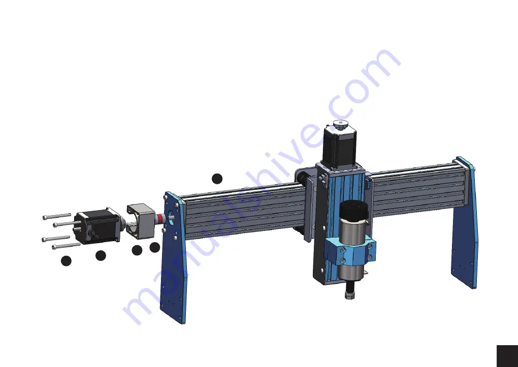
background image

15

Step 1:

 Install the flexible coupler to the X-Axis Leadscrew.

Be sure to loosen the grub screws to ensure the shaft full
seats inside.

Step 2:

 Just like the Base preparation. Prep your Stepper

Motor Mount + NEMA 23 Motor and 4 socket cap screws

and remember to position the mount with the opening
facing towards the rear of the gantry.

1

7

35

Step 3:

 Mount the assembly to the X-Axis. Tighten the

grub screws on the coupler.  Manually twist the wheel
on the Stepper Motor to verify smooth movement of the
Gantry on the X-Axis.

32

6

Summary of Contents for Genmitsu PROVerXL 4030

Page 1: ...V1 0 Aug 2020 USER MANUAL Genmitsu PROVerXL 4030 CNC Router...

Page 2: ...01 Welcome Disclaimer Specifications Part 1 Unboxing Part 2 Mechanical installation Part 3 Wiring Part 4 Software Setup Part 5 Test Project Part 6 Z Probe Setup 02 03 04 05 10 24 29 32 34 Contents...

Page 3: ...r Windows Sample files Please visit SainSmart Online Resource Center installing drivers and software for your CNC https docs sainsmart com proverxl 4030 The driver and software can also be found on th...

Page 4: ...nctions or damage to the machine The PROVerXL 4030 utilizes a high amp power supply It is recommended that you do not plug the CNC Router into an extension cord or power strip as it may damage the mac...

Page 5: ...Speed Control Button C Beam Linear Rail Machine Weight Package Weight Color Supported OS Software Frame Material 400 x 300 x 110mm NEMA23 115V 230V 8 5A 115V 4A 230V 12000r min DC24V 300W Leadscrew T...

Page 6: ...2 4 NEMA 23 Stepper Motor 6 3 4 Spindle Collet 7 8 4 Stepper Motor Mount Drag Chain Mount Mechanical Parts List Please make sure all the following parts are included If you are missing any part or hav...

Page 7: ...hain Mount 2 Drag Chain Mount Cable Management MDF Spoil Board 12 Electrical Parts List USB Cable A B 16 17 Power Cable US 1 2M PROVerXL Control Center 15 Bakelite Sheet 175 x 100 x 5mm 13 MDF Board 1...

Page 8: ...Kit 30 Degree 0 2mm Cutting area 3 175 Diameter 20 22 23 18 4 Material Clamp 21 10 Nano Blue Coat Bits 3 175mm Shank Cutting Edge Diameter 0 8 3 0mm 5 Allen Wrench 2 0mm 2 5mm 3 0mm 4 0mm 5 0mm Wrench...

Page 9: ...mm Socket Cap Screw Screws Other Parts List 31 8 M5 x 50mm Socket Cap Screw 35 3 Coupler 36 37 10 5mm Spring Washer 10 5mm Flat Washer 32 4 M5 x 55mm Socket Cap Screw 33 2 M4 x 6mm Socket Cap Screw 34...

Page 10: ...ies to make your CNC experience better You can find them on www sainsmart com Save 10 with discount code PROVerXL Router Bits Holder Storage Case CNC Router Bits Essential Kit Resin Board for CNC Engr...

Page 11: ...Mechanical installation 31 8 M5 x 50mm Socket Cap Screw 2 NEMA 23 Stepper Motor 6 7 2 Stepper Motor Mount 2 1 Preparing your Base Assembly What you will need Y Axis Base Assembly 2 22 Allen Wrench 35...

Page 12: ...ew to ensure the Lead Screw will completely seat inside Step 3 Tighten 2 M6 x 16mm screws to secure the lead screw mount Step 4 Next comes the Motor Mounts Stepper Motor Lay the Stepper Mount on your...

Page 13: ...ront and back of the machine Be sure the board is right side up Threaded Inserts should be towards the bottom if you install it in reverse the mounting screws will protrude from the top of the spoil b...

Page 14: ...13 29 5 30 12 2...

Page 15: ...14 2 3 Preparing your X Axis Gantry 2 NEMA 23 Stepper Motor 6 What you will need 32 4 M5 x 55mm Socket Cap Screw X Axis Spindle Z Axis Assembly 1 7 Stepper Motor Mount 35 Coupler 22 Allen Wrench...

Page 16: ...preparation Prep your Stepper Motor Mount NEMA 23 Motor and 4 socket cap screws and remember to position the mount with the opening facing towards the rear of the gantry 1 7 35 Step 3 Mount the assemb...

Page 17: ...ill need 28 2 M5 x 8mm Socket Cap Screw X Axis Spindle Z Axis Assembly 1 9 Drag Chain Mount Step 1 Position the X Axis Limiter to the rear of the Spindle Carriage as shown in the diagram Install the b...

Page 18: ...17 28 9...

Page 19: ...in the diagram Each carriage has an acrylic plate that will hold the gantry at the appropriate height Install the gantry using a 5mm washer 5mm spring washer then M5 x 16mm screw as shown in the diag...

Page 20: ...19 36 37 29...

Page 21: ...Align the T Slot nuts with the bracket the screws and nuts will be positioned on the top 2 channels of the C Beam Secure the bracket with the screws Step 2 Position the Drag Chain as shown in the diag...

Page 22: ...21 11 28 28 27 8 33...

Page 23: ...n the diagram Attach the bracket with 2 M6 x 10mm socket cap screws Step 2 Install the bracket to the carriage as shown in the diagram using 2 M4 x 8mm socket cap screws Step 3 Position the drag chain...

Page 24: ...23 10 10 34 37 36 29 11 Congratulations Now your PROVerXL machine body is fully assembled...

Page 25: ...rriage Using the labeled cable ends you need to connect the Z Axis Limit Switches to the Cable whip and wire the Spindle there is no requirement for which color goes onto which side of the spindle Ste...

Page 26: ...Y2 and run that to the left side while reserving the shorter cable marked X for the X Axis Motor and finally the medium length cable Y1 for the right side Y Axis motor Y2 to Left Motor and Y1 to Right...

Page 27: ...res from the Cable Whip Looks like central image above Power Voltage Switch X Axis Motor Y Axis Y2 Y Axis Y1 Motor Z Axis Motor Spindle Z Probe Z Limit Switch Y Limit Switch X Limit Switch Laser Modul...

Page 28: ...er Input Power ON Power OFF Offline controller Note Only connect to our offline controller Emergency stop switch interface Z Zero Tool interface X limit switch Y limit switch Z limit switch Descriptio...

Page 29: ...the threaded rods and lubricating as needed Ensure cables connecting the Z Axis and Spindle are not obstructed and mill move freely along the Z and X axis Check limit switch connections and all motor...

Page 30: ...29 Driver installation Part 4 Software Setup 1 Driver Installation Install the driver software Driver CH340SER exe...

Page 31: ...k Start Right click Computer Select Manage Select Device Manager from left pane In the tree expand Ports COM LPT Your machine will be the USB Serial Port COMX where the X represents the COM number for...

Page 32: ...ler First time use will require you setup the appropriate COM PORT and Baud rate Step 1 Software should automatically select the port number Step 2 If it does not recognize automatically select the Ba...

Page 33: ...heel can be enlarged or reduced If you cannot see anything you need to change to a computer with support for OpenGL2 0 graphics cards Open G code Send G code Command input box Send command Manual oper...

Page 34: ...nel move the spindle to the starting point of the engraving so that the tool and the workpiece just touch 3 Click ZeroXY Zero Z Clear the XYZ axis coordinate 4 Click Send running G code 3 About firmwa...

Page 35: ...Probe G code G90G21G38 2Z 50F100 G92 Z14 G0 Z25 After editing G90G21G38 2Z 50F100 G92 Z20 17 G0 Z28 Step 1 Probe commands editing Z14 is the height of the tool setting block which requires actual mea...

Page 36: ...35 Step 2 Probe commands filled in Grblcontrol Candle Fill the Commands here...

Page 37: ...36 Step 3 Connect the probe tool to the controller probe interface Step 4 Click the Z probe button Z axis automatic tool to zero Click the Z probe button...

Page 38: ...f may not be reproduced or used in any manner whatsoever without the written permission of the publisher except for the use of brief quotations embodied in critical reviews and certain other noncommer...

Page 39: ...support sainsmart com www sainsmart com Vastmind LLC 5892 Losee Rd Ste 132 N Las Vegas NV 89081 Genmitsu Desktop CNC Laser...

Reviews: