3.
SERVICE
3.1.
MAINTENANCE
PREVENTIVE MAINTENANCE
If SAILOR RT2048 has been installed in a proper way the maintenance can be reduced to an overhaul at each visit
of the service staff. Then inspect the set, the antenna, cables, and plugs for mechanical damages, salt deposits,
corrosion, and any foreign material. Owing to its traditional structure, the SAILOR RT2048 has a long lifetime, but
it must always be carefully checked at intervals not exceeding 12 months - dependent on the conditions under which
the set is working. The set must be brought to the service workshop to be tested.
Along with each set a TEST-SHEET is delivered in which all the measurements, made in the test department of
the factory, are listed. If the control measurings made in the service workshop should not show the same values
as those listed in the test-sheet, the set must be adjusted as specified in the ADJUSTMENT PROCEDURE.
3.2.
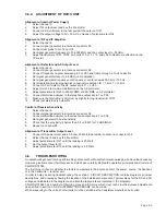
ALIGNMENT INSTRUCTIONS
INTRODUCTION
The measuring values indicated in paragraph 2 of CIRCUIT DESCRIPTION AND SCHEMATIC DIAGRAMS are
typical values and as indicated it will be necessary to use instruments in absolute conformity with the below list:
3.3.
PROPOSAL FOR NECESSARY MEASURING INSTRUMENTS
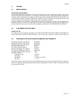
VHF Signal Generator type TF2015
MARCONI
FM Modulation Meter type TF2303
MARCONI
Distortion Analyzer type TF2337A
MARCONI
AF Voltmeter type VT-121
TRIO
Tone Generator type PM5107
PHILIPS
Electronic Multimeter type PM2505
PHILIPS
RF Directional Wattmeter Model 43
BIRD SOW
Load with 30 dB Attenuator type 8321
BIRD
Frequency Counter:
Frequency range
>175 Mhz
Sensitivity
<100 mv
Impedance
>1 Mohm and 50 ohm
Accuracy
<1 - 10
-6
We can also recommend one of the new communication test sets introduced by several instruments manufacturers.
From S. P. Radio this high quality product will be tested and adjusted by means of a CMT communication tester
from Rohde and Schwarz.
RT2048
Page 3-1
Summary of Contents for RT2048 VHF
Page 1: ...INSTALLATION MANUAL SAILOR RT2048 VHF ...
Page 4: ......
Page 11: ...1 INTRODUCTION RT2048 Page 1 7 9403 BLOCK DIAGRAM ...
Page 12: ......
Page 22: ...2 INSTALLATION RT2048 Page 2 10 9346 626945 625473 ...
Page 24: ...2 INSTALLATION RT2048 2 8 REAR VIEW OF VHF RT2048 25567 9350 Page 2 11 ...
Page 26: ......
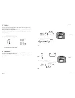
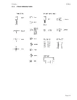
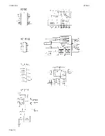
Page 31: ...3 Service RT2048 3 10 PIN CONFIGURATIONS Page 3 5 ...
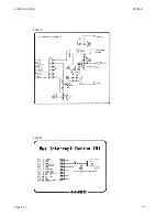
Page 32: ...3 SERVICE RT2048 Page 3 6 ...
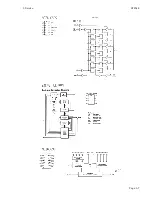
Page 33: ...3 Service RT2048 Page 3 7 ...
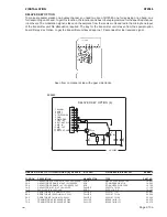
Page 34: ...3 SERVICE RT2048 Page 3 8 ...
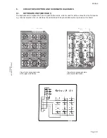
Page 38: ...5 CIRCUIT DESCRIPTION AND SCHEMATIC DIAGRAMS RT2048 Page 5 2 ...
Page 89: ......
Page 90: ...Thrane Thrane A S info thrane com www thrane com M2048GB Issue E 0820 ...

