3 SERVICE
RT2048
3.7.
REPLACEMENT OF COMPONENTS
When replacing transistors, diodes, resistors, capacitors and similar components you must use a small „pencil“
soldering iron of 30 to 75 Watt rating. The soldering must be performed rapidly to avoid overheating, and the use
of a tin sucker is recommended, as otherwise there is a risk that both the components and the printed circuit will
be spoiled.
3.8.
REPLACEMENT OF MODULES
If a fault has been found in a module, it may often be worthwhile to replace it and then repair it later on.
3.9.
NECESSARY ADJUSTMENTS AFTER REPLACEMENT OF MODULE
3.9.1.
REPLACEMENT OF RX/TX UNIT
1.
If a factory adjusted and tested module has to be inserted, just proceed with point 3.
2.
Follow the procedure described in section 3.5.2. ADJUSTMENT OF RX/TX UNIT.
3.
Follow the procedure Alignment of RX-filter control amplifier described in section 3.5.1. ADJUSTMENT OF
SYNTHESIZER UNIT.
3.9.2.
REPLACEMENT OF SYNTHESIZER UNIT
1.
If a factory adjusted and tested module has to be inserted, just proceed with point 3.
2.
Follow the procedure described in section 3.5.1. ADJUSTMENT OF SYNTHESIZER UNIT.
3.
Follow the procedure Alignment of RX-filter control amplifier described in session 3.5.1.
Page 3-4
Summary of Contents for RT2048 VHF
Page 1: ...INSTALLATION MANUAL SAILOR RT2048 VHF ...
Page 4: ......
Page 11: ...1 INTRODUCTION RT2048 Page 1 7 9403 BLOCK DIAGRAM ...
Page 12: ......
Page 22: ...2 INSTALLATION RT2048 Page 2 10 9346 626945 625473 ...
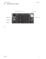
Page 24: ...2 INSTALLATION RT2048 2 8 REAR VIEW OF VHF RT2048 25567 9350 Page 2 11 ...
Page 26: ......
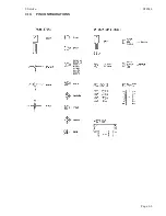
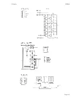
Page 31: ...3 Service RT2048 3 10 PIN CONFIGURATIONS Page 3 5 ...
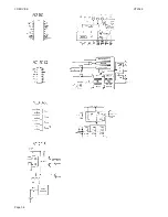
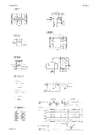
Page 32: ...3 SERVICE RT2048 Page 3 6 ...
Page 33: ...3 Service RT2048 Page 3 7 ...
Page 34: ...3 SERVICE RT2048 Page 3 8 ...
Page 38: ...5 CIRCUIT DESCRIPTION AND SCHEMATIC DIAGRAMS RT2048 Page 5 2 ...
Page 89: ......
Page 90: ...Thrane Thrane A S info thrane com www thrane com M2048GB Issue E 0820 ...

