2 INSTALLATION
RT2048
2.5.
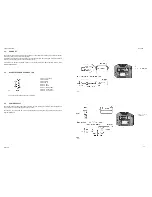
POWER CON EXT. LOUDSPEAKER
VIEW FROM MOUNTING SIDE
Pin No. 1 Ext. loudspeaker
Pin No. 2 Ext. mute*
Pin No. 3 +12V power supply
Pin No. 4 on/off for 24V supply
Pin No. 5 -12V power supply
Pin No. 6 Ext. loudspeaker
24914
* only active when option board pcb is installed.
If necessary a 4-8 ohm/6W external loudspeaker can be connected to pin No. 1 and pin No. 6 in the power connector
J01 (observe that there is DC voltage on both wires).
External loudspeakers SAILOR H2054 and H2074 are available.
2.6.
ANTENNAS
All common 50 ohm antennas, which cover the used frequency range with a reasonable standing wave ratio,
maximum 1.5, are available.
The antenna is connected to the set by means of a 50 ohm coaxial cable with low loss, e.g. RG213U. At the cable
end a PL259 plug is mounted.
The antenna must be placed as high and clear as possible. The horizontal distance to metal parts must be at least
one metre.
Thrane & Thrane has an antenna of the necessary specifications available. The mentioned antenna is character-
ized by small external dimensions. For further particulars see special brochure VHF AERIALS.
2.7.
SPECIAL OPTIONS
With a small modification in RT2048 the following options are available:
1.
K-switch function (used on river boats in Germany). Can be enabled by means
of the identity programming. US-button is changed to K-switch.
2.
With DISTRESS OPTION installed
Part no. 625661
a.
Distress output to CRY2001/2002.
3.
With SELCALL OPTION installed
Part no. 625660
a.
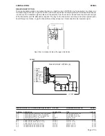
SELCALL RELAY, when the selcall has accepted a CQ or an individual call signal, the selcall
relay will turn on and short circuit two wires, which can be used for remote alarm.
Max. contact load: 100V AC/24V DC - 2A.
b.
AF TO INFORMATION DECODER, the circuit giving AF signals to the information decoder
is turned on when the set has accepted a CQ or an individual call signal. The circuit is turned
on/off by the microprocessor.
0820
Page 2-7
Summary of Contents for RT2048 VHF
Page 1: ...INSTALLATION MANUAL SAILOR RT2048 VHF ...
Page 4: ......
Page 11: ...1 INTRODUCTION RT2048 Page 1 7 9403 BLOCK DIAGRAM ...
Page 12: ......
Page 22: ...2 INSTALLATION RT2048 Page 2 10 9346 626945 625473 ...
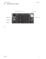
Page 24: ...2 INSTALLATION RT2048 2 8 REAR VIEW OF VHF RT2048 25567 9350 Page 2 11 ...
Page 26: ......
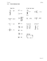
Page 31: ...3 Service RT2048 3 10 PIN CONFIGURATIONS Page 3 5 ...
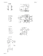
Page 32: ...3 SERVICE RT2048 Page 3 6 ...
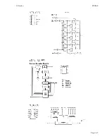
Page 33: ...3 Service RT2048 Page 3 7 ...
Page 34: ...3 SERVICE RT2048 Page 3 8 ...
Page 38: ...5 CIRCUIT DESCRIPTION AND SCHEMATIC DIAGRAMS RT2048 Page 5 2 ...
Page 89: ......
Page 90: ...Thrane Thrane A S info thrane com www thrane com M2048GB Issue E 0820 ...

