


4 SERVICE
RT2047 DSC - PART II
4.6
ADJUSTMENT PROCEDURE
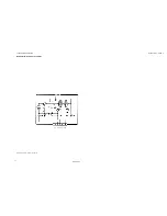
4.6.1
ADJUSTMENTS OF INTERFACE UNIT MODULE 6/600
ADJUSTMENT AND CONTROL OF VOLTAGE REGULATORS.
1.
Switch on the set.
2.
Select channel 28.
3.
Check 13.2V with a multi-meter on fuse F1-6 and P3-6 pin 9.
4.
Check 5V +0.2V with a multi-meter on U1-6 pin 3.
5.
Connect the multi-meter to Q9-6’s collector and adjust the 10V regulator with R65-6 to 10V +0.2V.
6.
Connect the multi-meter to Q11-6’s collector and key the transmitter.
7.
Adjust the PA-regulator with R68-6 to 8.4V + 0.2V.
8.
Connect the multi-meter to R6-6.
9.
Adjust RX-control voltage (VD
RX
) to 8V + 0.2V with R16-6.
ADJUSTMENT OF SELCALL TEST TONE
The procedure is described in the manual, INSTRUCTIONS FOR IDENTITY AND
SERVICE PROGRAMMING OF VHF RT2047, section 3.8: SELCALL TEST TONE
4.6.2
ADJUSTMENTS OF RX-SYNTHESIZER MODULE 200
1.
Select channel 28.
2.
Check the DC-control voltage on R217 with a multi meter to be 8V + 0.4V. If components have been
changed in the VCO-circuit, it is possible that the jump wire used for adjusting the VCO frequency
range has to be moved until the 8 + 0.4 V is achieved.
3.
Control the frequency F
L01
to RX with a frequency counter to be 140.600 MHz.
ADJUSTMENT OF F
L01
TO TX AND F
L01
TO RX.
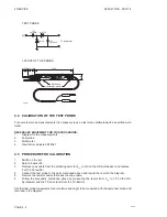
1.
Connect “calibrated” test probe to soldering point for F
L01
to TX.
2.
Adjust L202 until the core is 0.5 mm over the coil form and potentiometer R209 CCW to 1/3 of the
range.
3.
Adjust L206 to Max. deflection on the Tp meter.
4.
Select channel 6.
5.
Check the deflection on the Tp meter to be nearly the same as ch. 28. Otherwise obtain the level
on ch. 6 and ch. 28 to be nearly the same by adjusting L206.
6.
Connect test probe to soldering point for F
L01
to RX.
7.
Adjust L202 to Max. deflection on the Tp meter and secure that deflection on ch. 6 and ch. 28 are
nearly the same.
The levels measured with power meter (mW) and 50
W
impedance must be:
F
L01
to TX: 0.25 mW
F
L01
to RX: 5 mW +1.5 dB.
4.6.3
ADJUSTMENTS OF TX-EXCITER MODULE 300
1.
Select channel 28.
2.
Connect frequency counter to the top of T306.
3.
Adjust trimming capacitor C331 until the frequency counter shows 21MHz + 20Hz. Note that when
the transmitter is keyed you can measure on R332 and adjust R331 until the frequency counter
show 157400000 Hz + 150 hz.
4.
Check the clock frequency on microprocessor to be 2.1 MHz on FP301 .
5.
Check the DC-control voltage on R344 to be 8 + 0.4V. If components have been changed in the
VCO-circuit it is possible that the jump wire used for adjusting the VCO frequency range has to be
moved until the 8 + 0.4V is achieved. (With the Transmitter Keyed)
PAGE 4-3
9545
Summary of Contents for RT2047
Page 1: ...S P RADIO A S AALBORG DENMARK TECHNICAL MANUAL FOR COMPACT VHF RT2047 D ...
Page 2: ......
Page 5: ...RT2047 DSC PART I CONTENTS 1 GENERAL INFORMATION 1 1 1 1 INTRODUCTION 1 1 ...
Page 6: ......
Page 8: ......
Page 10: ......
Page 24: ......
Page 30: ...1 GENERAL INFORMATION RT2047 DSC PART II PAGE 1 6 9543 ...
Page 32: ......
Page 34: ......
Page 46: ...2 CIRCUIT DESCRIPTION RT2047 DSC PART II PAGE 2 12 9543 ...
Page 50: ...2 CIRCUIT DESCRIPTION RT2047 DSC PART II 9543 PAGE 2 16 ...
Page 66: ...9546 ...
Page 67: ...2 CIRCUIT DESCRIPTION RT2047 DSC PART II 9546 PAGE 2 33 32162 ...
Page 81: ......
Page 82: ......
Page 84: ......
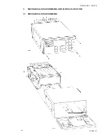
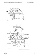
Page 86: ...3 MECHANICAL DISASSEMBLING AND MODULE LOCATION RT2047 DSC PART II PAGE 3 2 9545 ...
Page 88: ......
Page 90: ......
Page 98: ...4 SERVICE RT2047 DSC PART II PAGE 4 8 9545 ...
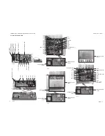
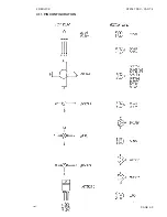
Page 99: ...4 SERVICE RT2047 DSC PART II 4 11 PIN CONFIGURATION 9545 PAGE 4 9 ...
Page 109: ...RT2047 DSC PART II CONTENTS 5 PARTS LISTS 5 1 9546 ...
Page 110: ......
Page 124: ......


