


2 CIRCUIT DESCRIPTION
RT2047 DSC - PART II
2.6.7
PA REGULATOR
By means of the PA regulator it is possible to adjust the output power of the transmitter. When the output
from U3/2-6 is changed from O to 5V, Q7-6 is turned off. Thus Q8-6 is turned on and then also Q2-6 and
Q1-6 and the output voltage rises. When the voltage at the base of Q8-6 is equal to the voltage on the
base of Q7-6 the current in Q8-6 is reduced and then also in Q2-6 and Q1-6 and the output voltage
stabilises. The output power from the TX POWER AMPLIFIER is adjusted by changing the output voltage
of the PA REGULATOR with R68-6. When reduced output power is chosen (0W mode) the µC turns PB5
to 0 V and the reference voltage to the regulator will be lowered. It can be adjusted at R29-6, and thus
also the reduced output power.
2.6.8
RX FILTER CONTROL AMPLIFIER
The control voltage from the RX VCO is turned into a control voltage to the capacity diodes in the band
pass filters in the receiver.
2.6.9
MICROPHONE AMPLIFIER
The amplifier consists of three stages. In the first stage the signal is preemphasized. In the next stage
the signal is clipped when the input signal is big enough, and in the last stage the signal is deemphasize
before it is led to the modulator in the TX EXCITER. The deemphasizing is necessary because it is a phase
modulator.
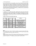
2.6.10 SQUELCH CIRCUIT
The signal from the receiver is fed to the active high pass filter U5/1-6. The filter attenuates signals below
10 KHz which means that talk will not be detected. The output of the filter is fed to the clipper Q15-6 and
the detector comprising the capacitor C45-6, the diodes D13-6, D14-6, and the resistors R3/1-6 and R5/
1-6. The rectified noise level is compared with a reference level in the voltage comparator U15/2-6. When
the noise level is higher than the reference level, the output will be low. This output is connected to PD7
on the µC, which will turn off the AF by means of U18-6, except if the squelch setting is 0 ( in the display),
The correspondence between the number in the display and the latch U4-6 can be seen below:
64
:LWKRXWFDUULHU
:LWKFDUULHU
%%%%
%%%%
0
1 1 1 1
1 1 1 1
1
1 1 1 0
1 1 1 1
2
1 1 0 1
1 1 1 0
3
1 1 0 0
1 1 0 1
4
1 0 1 0
1 1 0 0
5
1 0 0 0
1 0 1 0
6
0 1 1 0
1 0 0 0
7
0 1 0 0
0 1 1 0
8
0 0 1 0
0 1 0 0
PAGE 2-18
9543
Summary of Contents for RT2047
Page 1: ...S P RADIO A S AALBORG DENMARK TECHNICAL MANUAL FOR COMPACT VHF RT2047 D ...
Page 2: ......
Page 5: ...RT2047 DSC PART I CONTENTS 1 GENERAL INFORMATION 1 1 1 1 INTRODUCTION 1 1 ...
Page 6: ......
Page 8: ......
Page 10: ......
Page 24: ......
Page 30: ...1 GENERAL INFORMATION RT2047 DSC PART II PAGE 1 6 9543 ...
Page 32: ......
Page 34: ......
Page 46: ...2 CIRCUIT DESCRIPTION RT2047 DSC PART II PAGE 2 12 9543 ...
Page 50: ...2 CIRCUIT DESCRIPTION RT2047 DSC PART II 9543 PAGE 2 16 ...
Page 66: ...9546 ...
Page 67: ...2 CIRCUIT DESCRIPTION RT2047 DSC PART II 9546 PAGE 2 33 32162 ...
Page 81: ......
Page 82: ......
Page 84: ......
Page 86: ...3 MECHANICAL DISASSEMBLING AND MODULE LOCATION RT2047 DSC PART II PAGE 3 2 9545 ...
Page 88: ......
Page 90: ......
Page 98: ...4 SERVICE RT2047 DSC PART II PAGE 4 8 9545 ...
Page 99: ...4 SERVICE RT2047 DSC PART II 4 11 PIN CONFIGURATION 9545 PAGE 4 9 ...
Page 109: ...RT2047 DSC PART II CONTENTS 5 PARTS LISTS 5 1 9546 ...
Page 110: ......
Page 124: ......


