


1 GENERAL INFORMATION
RT2047 DSC - PART II
1.4
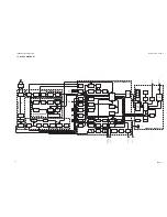
PRINCIPLE OF OPERATION
1.4.1
FREQUENCY GENERATION
The frequencies are generated from a crystal oscillator operating on 21 MHz. The 21 MHz is divided in
the REFERENCE DIVIDER to 2.1 MHz which is the input to the RX-REFERENCE DIVIDER and also the
clock-signal for the microcomputer on the Interface Unit. In the RX-REFERENCE DIVIDER the 2.1 MHz
is divided by 168 to 12.5 KHz which is reference for the PHASE DETECTOR. This makes it possible to
change the frequency from the RX-VCO with 12.5 KHz intervals.
The signal from the RX-VCO is divided in a PRESCALER which divides by 33 until the A-COUNTER has
reached zero and then it divides by 32. The N-COUNTER divides the output from the PRESCALER, and
the output is led to the PHASE-DETECTOR, and here it is compared with the 12.5 KHz. If there is a
difference an error voltage will be generated. This is integrated in the LOOP-FILTER and the output of
this filter controls the RX-VCO. The frequency of the RX-VCO is the receiving frequency minus the
intermediate frequency.
f
LO1
= f
RX
- f
1IF
= f
RX
-21.4 MHz
The output from the RX-VCO is mixed with the output from the TX-VCO which is in lock when it is 16.8
MHz above the RX-VCO. This means that the receiver always is 4.6 MHz above the transmitter, namely
21.4 - 16.8 = 4.6; and this difference is equal to the duplex distance. The 16.8 MHz from the MIXER is
divided by 32 to 525 KHz, which is compared with the 21 MHz divided by 40 in the REFERENCE DIVIDER.
The error voltage is integrated in the LOOP-FILTER, and the output of this filter controls the TX-VCO.
1.4.2
RECEIVER
The antenna-signal is led through the duplex-filter and the antenna relay to the RF-AMPLIFIER. The
bandpass filters are tuned by means of capacitor-diodes which are controlled by means of a DC-voltage
which is derived from the control-voltage to the RX-VCO. In the FIRST MIXER the antenna signal is mixed
with the output from the RX-VCO to the intermediate frequency 21.4 MHz. In the integrated IF circuit, the
first IF frequency on 21.4 MHz is mixed with a crystal oscillator signal on 20.945 MHz to reach the second
IF frequency on 455 kHz. This signal is filtered in the ceramic filter, before it is amplified and detected in
the integrated IF-circuit. The audio frequency signal is amplified and led through an active filter providing
the frequency response further to the telephone amplifier and the AF power amplifier.
1.4.3
TRANSMITTER
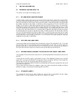
The microphone signal is led through the MICROPHONE AMPLIFIER where the necessary amplification,
limiting, and filtering takes place. The limiting is done by a clipper. The signal from the MICROPHONE
AMPLIFIER is led to the LOOP-FILTER, where the phase modulation of the transmitter takes place. As
the TX-VCO oscillates directly on the transmitting frequency, the signal only has to be amplified. This is
done in the TX-BUFFER, PA-DRIVER, and the PA-POWER AMPLIFIER. The power supply for the PA-
driver is adjustable, and is used for adjusting the output power. The harmonics of the output is filtered in
HARM-FILTER , before it is led through the ANTENNA-RELAY and the DUPLEX-FILTER to the antenna.
1.4.4
THE MICROCOMPUTERS
The µC on the Interface Unit is taking care of calculating the dividing figure for the synthesizer, reading
from and to the EEPROMs, controlling the squelch and volume functions, and controlling the selcall filter.
The µC on the Keyboard Unit is taking care of the keyboard scanning, the input from the handset key and
the display drivers as well as the Dual Watch and Scanning functions. The keyboard µC is also handling
the serial SP VHF-BUS communication with external devices such as the VHF DSC - RM2042. The
communication between the two µC’s is accomplished by a RS232C -type serial connection.
PAGE 1-5
9543
Summary of Contents for RT2047
Page 1: ...S P RADIO A S AALBORG DENMARK TECHNICAL MANUAL FOR COMPACT VHF RT2047 D ...
Page 2: ......
Page 5: ...RT2047 DSC PART I CONTENTS 1 GENERAL INFORMATION 1 1 1 1 INTRODUCTION 1 1 ...
Page 6: ......
Page 8: ......
Page 10: ......
Page 24: ......
Page 30: ...1 GENERAL INFORMATION RT2047 DSC PART II PAGE 1 6 9543 ...
Page 32: ......
Page 34: ......
Page 46: ...2 CIRCUIT DESCRIPTION RT2047 DSC PART II PAGE 2 12 9543 ...
Page 50: ...2 CIRCUIT DESCRIPTION RT2047 DSC PART II 9543 PAGE 2 16 ...
Page 66: ...9546 ...
Page 67: ...2 CIRCUIT DESCRIPTION RT2047 DSC PART II 9546 PAGE 2 33 32162 ...
Page 81: ......
Page 82: ......
Page 84: ......
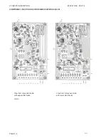
Page 86: ...3 MECHANICAL DISASSEMBLING AND MODULE LOCATION RT2047 DSC PART II PAGE 3 2 9545 ...
Page 88: ......
Page 90: ......
Page 98: ...4 SERVICE RT2047 DSC PART II PAGE 4 8 9545 ...
Page 99: ...4 SERVICE RT2047 DSC PART II 4 11 PIN CONFIGURATION 9545 PAGE 4 9 ...
Page 109: ...RT2047 DSC PART II CONTENTS 5 PARTS LISTS 5 1 9546 ...
Page 110: ......
Page 124: ......


