2 INSTALLATION
RT2047 DSC - PART I
PAGE 2-9
2.4
HANDSET
The handset can be placed anywhere near the VHF set. The cable is nine cored and connected to the
rear plate through a 9 pin Sub D connector with lock nuts.
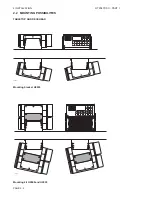
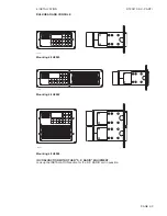
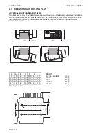
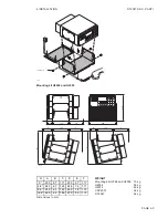
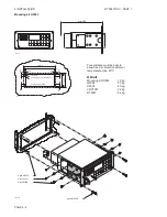
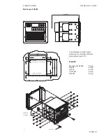
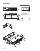
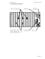
Installation of the cable, see the drawings of the mounting brackets, section 2.3 DIMENSIONS AND
DRILLING PLAN. The cable grommet must be placed in the most convenient groove in the mounting
bracket.
If more than one handset is needed, see section 2.12. and 2.13. in part II, SPECIAL INSTALLATION
WITH 2 OR 3 MICRO TELEPHONES.
2.5
MICROTELEPHONE CONNECTOR
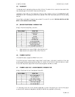
Wiring of the micro telephone connector.
3,1180%(5
)81&7,21
1
Tel
2
Ground
3
Ground
4
Microphone
5
Handset key
6
AF from RX buffer
7
Interrupt/Distress cry *
8
Serial input/output
9
+13V Internal/Phone Patch**
*/
Signal selection on jumper P608 on the Interface-unit.
**/
Signal selection on jumper P934 on the Filter-unit
2.6
POWER SUPPLY
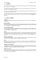
The standard power supply for RT2047 is 12V DC .
For 24V DC supply an external power supply N418 ( switch mode ) or the N420 a 24V DC to 13.2V DC
serial regulator can be used, see part II, section 2.14 . and 2.15 .For 110V AC, 127V AC, 220V AC or 237V
AC an external power supply N163S must be used together with N418 or N420 .
2.7
POWER AND EXT. LOUDSPEAKER CONNECTOR
Wiring of the power and ext. loudspeaker connector.
3,1180%(5
)81&7,21
1
+Ext. loudspeaker*
2
No connection
3
+12V Power Supply
4
ON/OFF for 24V Supply
5
-12V Power Supply
6
-Ext. loudspeaker*
*/ If necessary a 4-8 ohm (4 W) external loudspeaker can be connected to pin 1 and 6 of the power
connector J802. External loudspeakers H2054 and H2074 are available for this option.
Summary of Contents for RT2047
Page 1: ...S P RADIO A S AALBORG DENMARK TECHNICAL MANUAL FOR COMPACT VHF RT2047 D ...
Page 2: ......
Page 5: ...RT2047 DSC PART I CONTENTS 1 GENERAL INFORMATION 1 1 1 1 INTRODUCTION 1 1 ...
Page 6: ......
Page 8: ......
Page 10: ......
Page 24: ......
Page 30: ...1 GENERAL INFORMATION RT2047 DSC PART II PAGE 1 6 9543 ...
Page 32: ......
Page 34: ......
Page 46: ...2 CIRCUIT DESCRIPTION RT2047 DSC PART II PAGE 2 12 9543 ...
Page 50: ...2 CIRCUIT DESCRIPTION RT2047 DSC PART II 9543 PAGE 2 16 ...
Page 66: ...9546 ...
Page 67: ...2 CIRCUIT DESCRIPTION RT2047 DSC PART II 9546 PAGE 2 33 32162 ...
Page 81: ......
Page 82: ......
Page 84: ......
Page 86: ...3 MECHANICAL DISASSEMBLING AND MODULE LOCATION RT2047 DSC PART II PAGE 3 2 9545 ...
Page 88: ......
Page 90: ......
Page 98: ...4 SERVICE RT2047 DSC PART II PAGE 4 8 9545 ...
Page 99: ...4 SERVICE RT2047 DSC PART II 4 11 PIN CONFIGURATION 9545 PAGE 4 9 ...
Page 109: ...RT2047 DSC PART II CONTENTS 5 PARTS LISTS 5 1 9546 ...
Page 110: ......
Page 124: ......

