4 SERVICE
RT2047 DSC - PART II
PAGE 4-1
4
SERVICE
4.1
MAINTENANCE
PREVENTIVE MAINTENANCE
If RT2047 has been installed properly the maintenance can be reduced to an overhaul at each visit of our
service staff. Inspect the set, the antenna, cables and plugs for mechanical damages, salt deposits,
corrosion and any foreign materials. Due to its solid structure the RT2047 has a long lifetime, but due to
the operating conditions it should be carefully controlled at maximum 12 month intervals. The set should
be taken to a certified service point for testing. Along with each set a “Test-sheet” is delivered in which
all the measurements made in the test department of the factory are listed. If the control measurements
made in the service workshop should show other values then those listed in the “Test-sheet”, the set must
be adjusted as specified under Adjustment Procedure.
4.2
ADJUSTMENT INSTRUCTIONS
INTRODUCTIONS
The measuring values indicated in paragraph 2 concerning circuit description and schematic diagrams
are typical values and it will be necessary to use instruments in absolute conformity with the list below:
4.3
PROPOSAL FOR NECESSARY MEASURING INSTRUMENTS
VHF Signal Generator type TF2015
MARCONI
FM Modulation Meter type TF2303
MARCONI
Distortion Analyzer type TF2337A
MARCONI
AF Volmeter type VT-121
TRIO
Tone Generator type PM5107
PHILIPS
Electronic Multi meter type PM2505
PHILIPS
RF Directional Watt meter Model 43
BIRD
50W Load with 30 dB Attenuator type 8321 BIRD
FREQUENCY COUNTER:
Frequency range
> 175 MHz
Sensitivity
< 100 mV
Impedance
> 1 M
W
& 50
W
Accuracy
< 1×10
-6
We also recommend the portable universal VHF test set from Radio Holland,
the Omnitester type RH-4316. This test set is designed especially for fast and accurate service of VHF
transceivers.
9545
Summary of Contents for RT2047
Page 1: ...S P RADIO A S AALBORG DENMARK TECHNICAL MANUAL FOR COMPACT VHF RT2047 D ...
Page 2: ......
Page 5: ...RT2047 DSC PART I CONTENTS 1 GENERAL INFORMATION 1 1 1 1 INTRODUCTION 1 1 ...
Page 6: ......
Page 8: ......
Page 10: ......
Page 24: ......
Page 30: ...1 GENERAL INFORMATION RT2047 DSC PART II PAGE 1 6 9543 ...
Page 32: ......
Page 34: ......
Page 46: ...2 CIRCUIT DESCRIPTION RT2047 DSC PART II PAGE 2 12 9543 ...
Page 50: ...2 CIRCUIT DESCRIPTION RT2047 DSC PART II 9543 PAGE 2 16 ...
Page 66: ...9546 ...
Page 67: ...2 CIRCUIT DESCRIPTION RT2047 DSC PART II 9546 PAGE 2 33 32162 ...
Page 81: ......
Page 82: ......
Page 84: ......
Page 86: ...3 MECHANICAL DISASSEMBLING AND MODULE LOCATION RT2047 DSC PART II PAGE 3 2 9545 ...
Page 88: ......
Page 90: ......
Page 98: ...4 SERVICE RT2047 DSC PART II PAGE 4 8 9545 ...
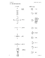
Page 99: ...4 SERVICE RT2047 DSC PART II 4 11 PIN CONFIGURATION 9545 PAGE 4 9 ...
Page 109: ...RT2047 DSC PART II CONTENTS 5 PARTS LISTS 5 1 9546 ...
Page 110: ......
Page 124: ......

