Chapter 3: Wiring
Firmware – S1043
Revision: 2 (9/98)
41
© Saftronics, Inc.
11
12(G)
13
14
15
16
17
25
26
27
33
18
19
20
1
2
3
4
5
6
7
8
21
22
23
9
10
Figure 3.19
Control Circuit Terminal Arrangement
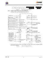
3.5.3
Control Circuit Terminal Connections (All Models)
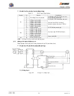
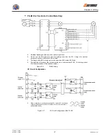
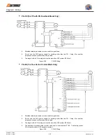
Connections to VG5 control circuit terminals are shown in
Figure 3.20
.
Factory presets are shown in parentheses. When driving an inductive load, such as a relay coil, always insert a flywheel
diode as shown in
Figure 3.18
.
Figure 3.20
Control Circuit Terminal Connections


